|
|
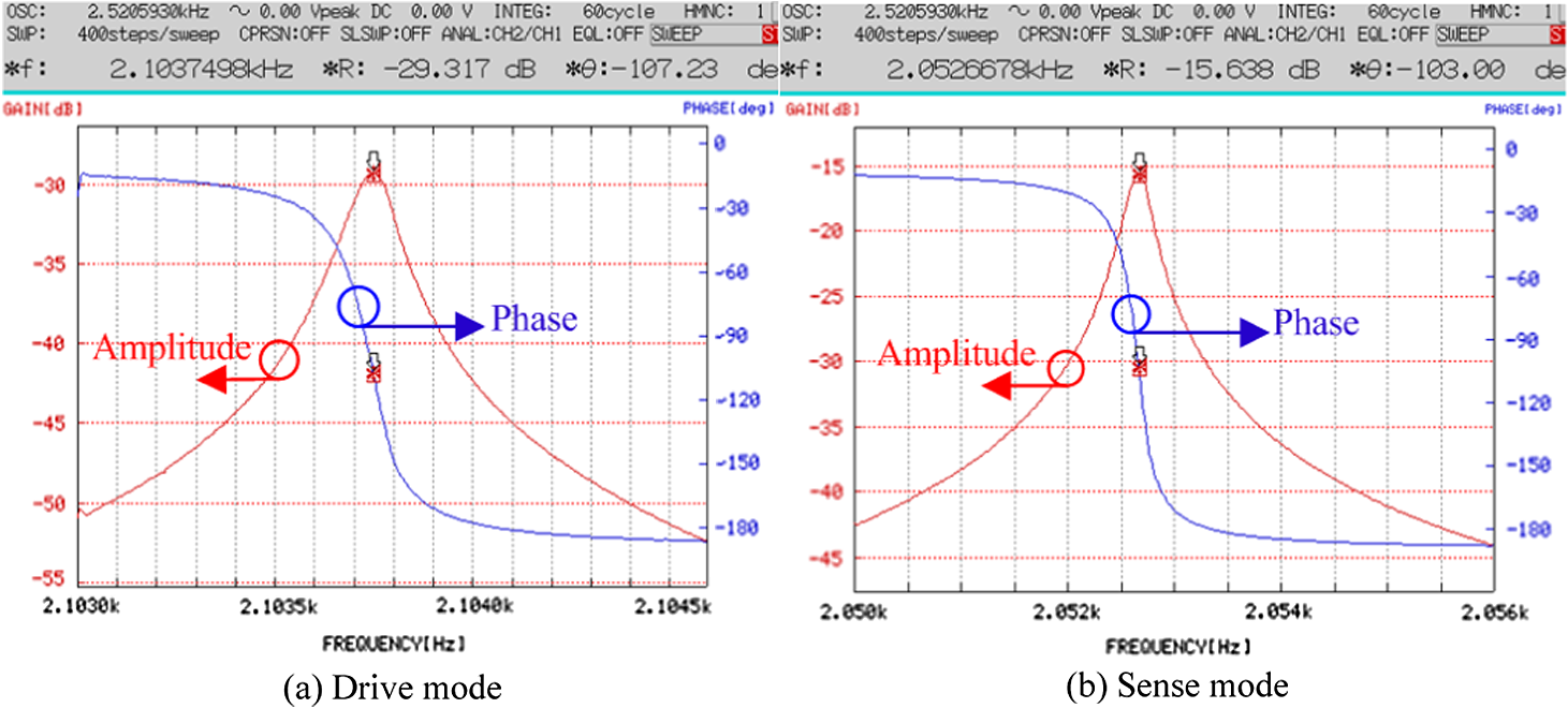
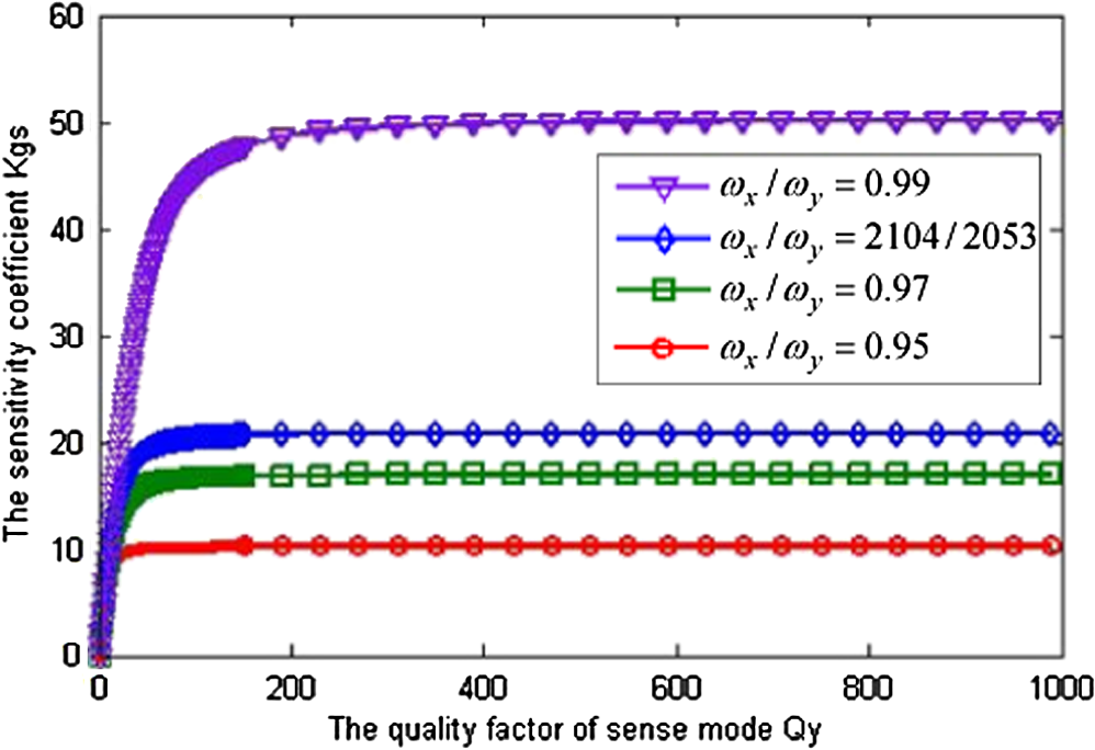
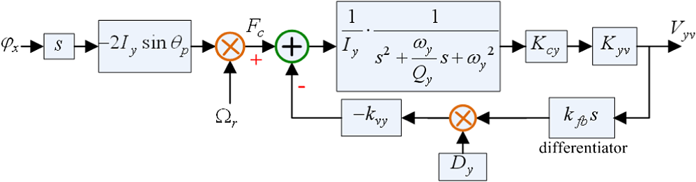
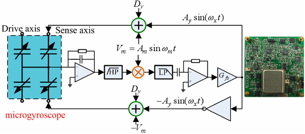
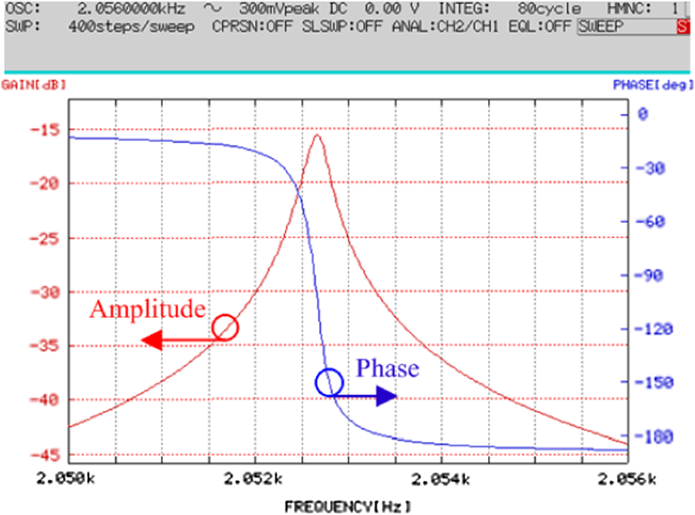
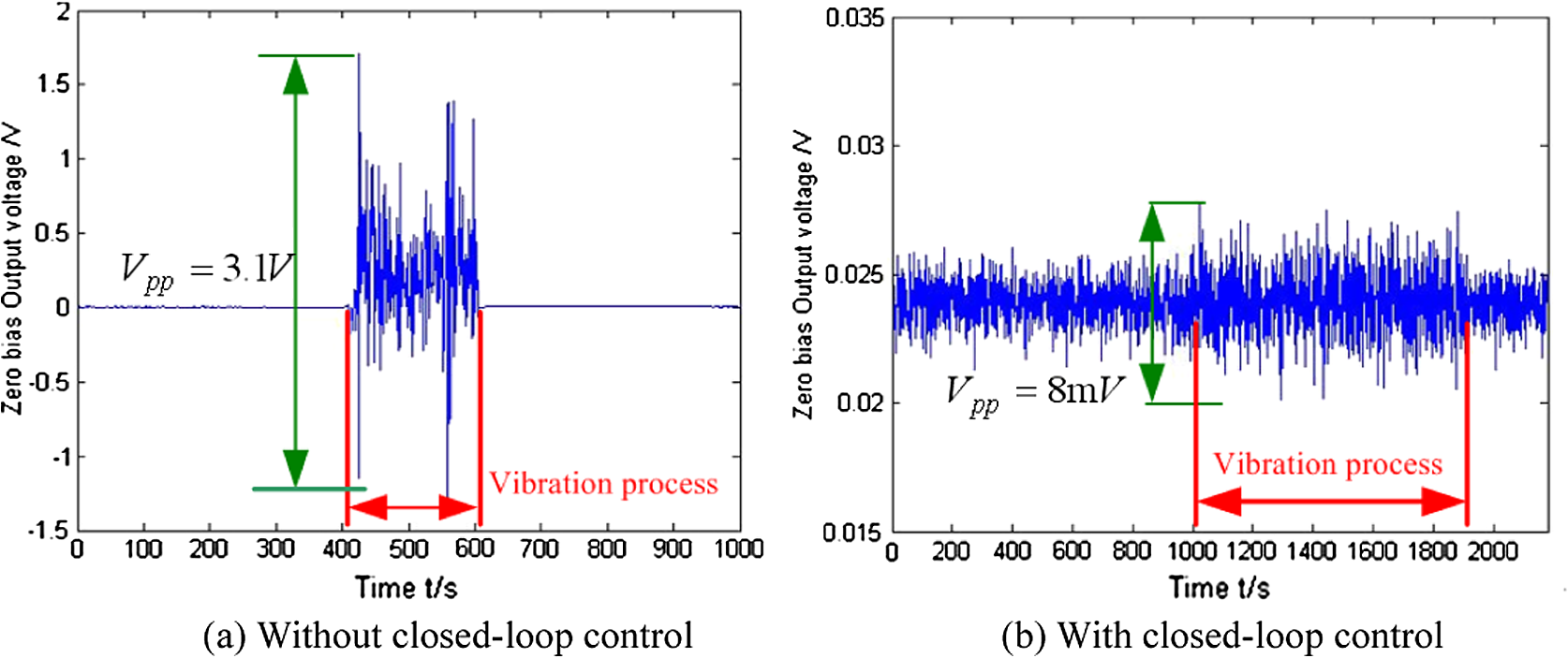
1.IntroductionThe operation of a vibratory microgyroscope is based on thetransfer of energy from drive mode vibrations to sense mode vibrations caused by the Coriolis effect.1,2 The vibration amplitude of the drive mode mostly defines the structural sensitivity of the microgyroscope, so a higher drive mode quality factor is always desired to both improve rate precision and lower power consumption. The most effective technique to increase the drive mode quality factor is sealing the microgyroscope in high vacuum. However, in doing so, the sense mode quality factor will be increased simultaneously. A higher sense mode quality factor will lead to a longer decay time of the free response and even self-oscillation of the sense mode vibration. Consequently, external vibration will cause huge output errors, and the mechanical performance of the microgyroscope is seriously degraded. A closed-loop control technique was presented to improve the mechanical performance of a vacuum-sealed microgyroscope. A velocity feedback loop was designed to increase the electric damping of sense mode vibrations. After analyzing the structural sensitivities of microgyroscopes with various sense mode quality factors, an optimized sense mode quality factor was suggested to improve the mechanical performance of the microgyroscope without sensitivity degradation. A feedback control circuit was fabricated, and experiments were carried out to validate this design. 2.Theoretical AnalysisThe structural implementation of the microgyroscope designed in this paper is shown in Fig. 1(a).3 It includes two proof masses and a slanted suspension cantilever. The microstructure is fabricated by TMAH anisotropic etching. The slanted cantilever is formed by {100} and {111} crystal planes as shown in Fig. 1(b).4 The drive mode is the “see-saw” oscillation of the masses in the gyroscope plane, caused by the bending of the cantilever. The sense mode is the anti-phase oscillation of the masses out of the gyroscope plane, caused by the torsion of the cantilever. The drive and sense electrodes are fabricated on the glass substrate beneath the microstructure. The fabricated structure is shown in Fig. 1(c). The structure was sealed in a metal package at 1 Pa atmospheric pressure by cold welding as shown in Fig. 1(d). Fig. 1Structural diagram of the designed microgyroscope; (a) structural implementation; (b) cross-section of the cantilever; (c) fabricated structure; (d) sealed microgyroscope. 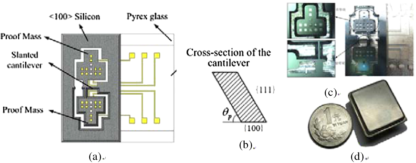 After vacuum sealing, the drive mode quality factor of this microgyroscope increased from 66 to 16,830, and the sense mode quality factor increased from 3 to 8052 simultaneously. The frequency responses of the fabricated microgyroscope were tested using frequency response analyzer FRA5087, and the results are shown in Fig. 2. The drive and sense mode frequencies were 2104 and 2053 Hz, respectively. The signal flow graph of this microgyroscope is shown in Fig. 3, where and are the DC voltages applied on the drive and sense electrodes, respectively, is the sinusoidal driving voltage applied on the drive electrodes, is the sinusoidal feedback voltage applied on the sense electrodes, and are voltage to moment conversion ratio of drive and sense axis, is the slanted angle of the cantilever of the microgyroscope, and are the inertia of the drive and sense mode, respectively, and are the resonant frequencies of drive and sense mode, respectively, and are the quality factors of drive and sense mode, respectively, is the input angular rate, and are the angular displacements of drive and sense mode vibration, respectively, and are displacement to capacitance conversion ratio of drive and sense axis, respectively, and and are the capacitive changes related to drive and sense mode vibration, respectively. In keeping with a technique reported in many researches, a closed-loop control technique was used to generate drive mode resonance with constant amplitude. So the angular displacement of the drive mode vibration could be assumed as . If the step input angular rate is , the differential equation for the sense mode angular displacement is For the vacuum sealed microgyroscope, the solution to Eq. (1) is expressed as where is the phase lag between the Coriolis force and sense mode vibration. is expressed asThe first term on the right-hand side of Eq. (2) is the forced response caused by the Coriolis effect. A coefficient is defined to express the structural static sensitivity of the microgyroscope as The relation ship between and for various is shown in Fig. 4. When the sense mode quality factor is very small, the structural sensitivity coefficient increases quickly with an increase of . Under the condition that the sensitivity coefficient will not increase with an increase of anymore and tend to be constant.The second term on the right-hand side of Eq. (2) is the free response of the sense mode. The time constant for the decay of the free response is A higher sense mode quality factor will lead to a longer decay time of the free response. For the fabricated microgyroscope in this paper, this time constant is 1.25s, which means that the output of the microgyroscope is very easily disturbed by external vibrations. In other words, the mechanical performance of the microgyroscope will degrade with the increase of the sense mode quality factor. 3.Feedback Loop DesignThe sense mode quality factor should be optimized to improve the mechanical performance of the high vacuum-sealed microgyroscope. The quality factor decreases as the damping force increases. Sealing the microstructure at a higher atmospheric pressure is not a good choice because the drive mode quality factor will decrease as well as the sense mode quality factor. Designing a feedback control loop to increase the electric damping of the sense mode vibration seems to be the best choice. As the damping force is related to the velocity of structural movement, a velocity feedback control loop is required to generate an electric damping force on the vibrating structure. The signal flow of the designed feedback control loop for the sense mode is shown in Fig. 5, where is the Coriolis force, is the capacitance to voltage conversion ratio of sense axis, and is the output signal of the capacitance to voltage conversion circuit for the sense mode vibration. A differentiator is used to transfer the displacement signal to velocity signal and is the feedback coefficient. The transfer function from to output voltage is The modified sense mode quality factor of the feedback system shown in Fig. 5 is expressed as The sense mode quality factor should be decreased to improve the mechanical performance of the vacuum sealed microgyroscope, but the structural sensitivity of the microgyroscope will degrade dramatically when the sense mode quality factor is very low. The optimized sense mode quality factor is suggested to be Under this condition, the sensitivity of microgyroscope only degrades 0.1% after using this feedback control technique. From Eqs. (8) and (9), the feedback coefficient required for this optimized sense mode quality factor is determined by 4.ExperimentThe sense mode closed-loop controlling scheme is designed as shown in Fig. 6. The measurement of the sense capacitance is made by the two equal amplitude, out-of-phase sinusoidal modulation signals, and , with the same frequency . In the meantime, DC voltage is added to the excitation signals in the sense electrodes. A differentiator is inserted between the low-pass filter and the amplifier . The output signals of the amplifier and the phase inverter following the amplifier are added to the top and bottom plates, respectively. An electric damping force will be generated on the sense axis, and the sense mode quality factor will be decreased. The frequency responses of this closed-loop system with various gains were tested using FRA5087. The results are shown in Fig. 7(a). The relationship between quality factor and is shown in Fig. 7(b). It can be seen that the quality factor of the closed-loop system decreased with an increase of the velocity feedback coefficient. Fig. 7Frequency responses and quality factor of sense mode with closed-loop control; (a) frequency responses with various ; (b) relationship between sense mode quality factor and . 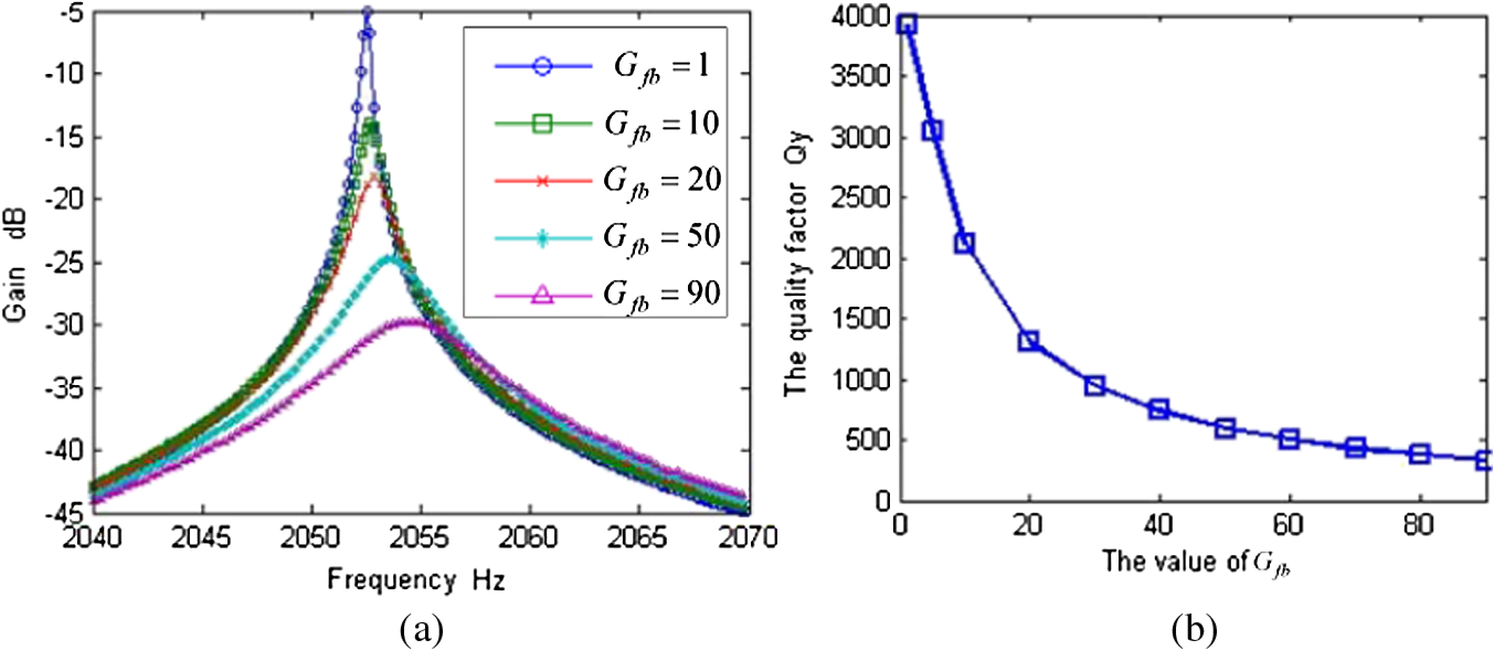 According to Eq. (9), the optimized sense mode quality factor was suggested to be 449. Using the feedback coefficient determined by Eq. (10), the sense mode quality factor of the microgyroscope with closed-loop control was tested to be 428 as shown in Fig. 8, which was very close to the target value. When a shock is applied on the microgyroscope, the output signals of the capacitance to voltage conversion circuit for the sense mode vibration are shown in Fig. 9. The decay time required for the microgyroscope was shortened from 3 to 0.5 s after using this closed-loop control technique. Fig. 9The output signals of the capacitance to voltage conversion circuit for the sense mode vibration when applying a shock.  The outputs of this microgyroscope were measured under external random vibration. The frequency range of the random vibration was 20 to and the vibration intensity was . The output errors of the microgyroscope without closed-loop control increased dramatically during external vibrations, as shown in Fig. 10(a), which means that this open-loop microgyroscope can hardly work in a vibrating environment. After using this closed-loop control technique, the output noise of the microgyroscope during external vibration was almost unchanged, as shown in Fig. 10(b). It can be concluded that the vibration-rejecting ability of the microgyroscope was obviously improved by this closed-loop control technique. 5.ConclusionsIn order to improve the mechanical performance of a microgyroscope sealed in high vacuum, a closed-loop control technique based on velocity feedback was designed to modify the sense mode quality factor of the microgyroscope without structural sensitivity degradation. Experimental results indicated that the sense mode quality factor was optimized from 8052 to 428, and the decay time of the sense mode free response was shortened from 3 to 0.5 s. The vibration-rejecting ability of the microgyroscope was obviously improved by this closed-loop control technique. AcknowledgmentsThis work was supported by National Natural Science Foundation of China (Grant No. 51005239) and National University of Defense Technology Foundation (No. JC12-03-04). The authors would like to thank the Laboratory of Microsystem, National University of Defense Technology, China, for equipment access and technical support. ReferencesA. A. TrusovA. R. SchofieldA. M. Shkel,
“Performance characterization of a new temperature-robust gain-bandwidth improved MEMS gyroscope operated in air,”
Sens. Actuat. A, 155
(1), 16
–22
(2009). http://dx.doi.org/10.1016/j.sna.2008.11.003 SAAPEB 0924-4247 Google Scholar
N.-C. TsaiC.-Y. SueC.-C. Lin,
“Micro angular rate sensor design and nonlinear dynamics,”
J. Micro/Nanolith. MEMS MOEMS, 6
(3), 033008
(2007). http://dx.doi.org/10.1117/1.2778645 JMMMGF 1932-5134 Google Scholar
X. Dingbang,
“High-performance micromachined gyroscope with a slanted suspension cantilever,”
J. Semiconduct., 30
(4), 044012
(2009). http://dx.doi.org/10.1088/1674-4926/30/4/044012 JSOEB4 1674-4926 Google Scholar
Z. Hou,
“Effect of axial force on the performance of micromachined vibratory rate gyroscopes,”
Sensors, 11
(1), 296
–309
(2011). http://dx.doi.org/10.3390/s110100296 SNSRES 0746-9462 Google Scholar
Biography |