|
|
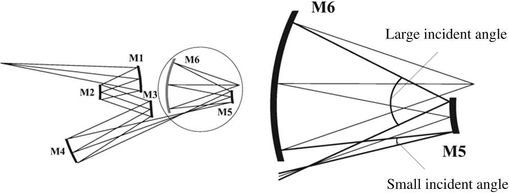
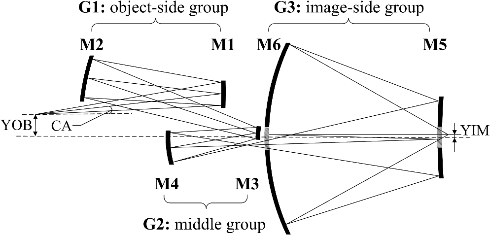
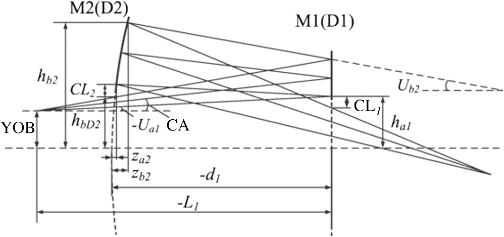
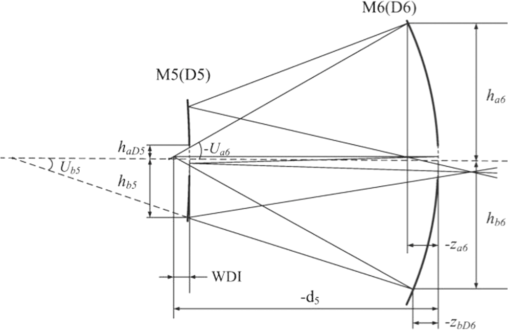
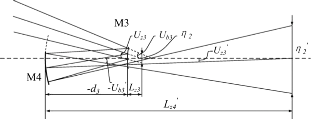
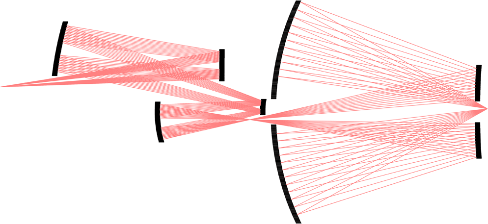
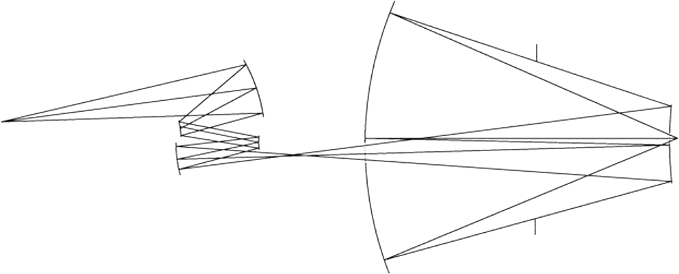
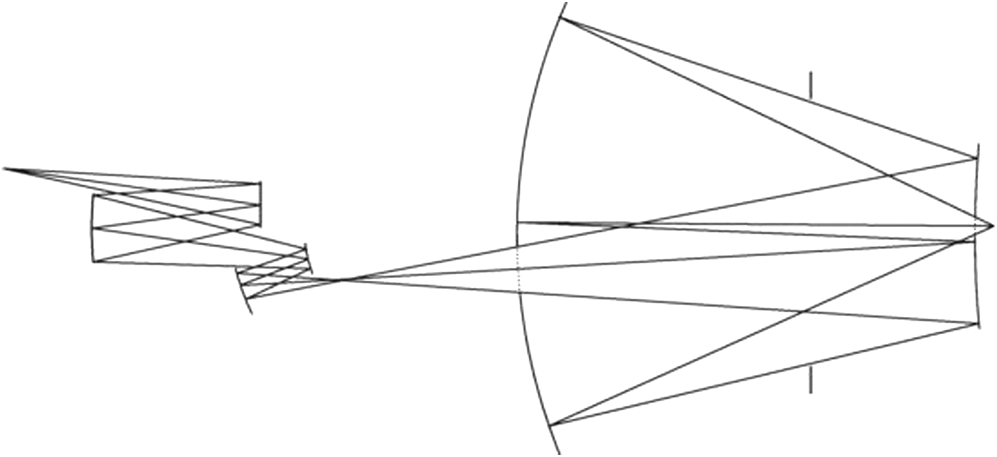
1.IntroductionProjection objective is a key component of an extreme ultraviolet (EUV) lithography tool. To achieve an 11-nm resolution, a higher numerical aperture (NA) of the objective system around 0.45 is required.1 The increase of the NA makes a traditional six-mirror design without obscuration inadequate to correct aberration. Under such a high NA, an eight-mirror design without obscuration could achieve the required imaging performance. However, the transmission would be reduced to of the six-mirror system and the integration and maintenance would be more difficult. The design with a central obscuration has a smaller difference of angles of the mirrors, which enables a well-designed correction for a six-mirror system.2,3 However, few design methods for the objective system with a central obscuration have been proposed in the past. We have developed a grouping design method with paraxial analysis.4,5 The multimirror projection objective without obscuration could be acquired with this method. In this paper, we extend the grouping design method to the design of a high-NA projection objective with central obscuration. Moreover, real ray analysis6 is used instead of paraxial analysis, which avoids the discrepancy of the ray path induced by paraxial approximation. In the design process, the whole system is divided into three mirror groups and each group is calculated under a specific design constraint. At first, the initial parameters of the object-side group are determined according to a nonobscuration constraint. To control the size of the obscuration, the ratio of obscuration on the last folding mirror (M5) and the exit mirror (M6) is taken as a design constraint of the image-side group. The initial parameters of the image-side group can be determined with the obscuration-ratio constraint. Once the parameters of the object-side and image-side groups are determined, all the parameters of the middle group can be calculated with the conjugation constraint based on real ray tracing equations and the Petzvalsum condition. Using real ray tracing analysis, the pupils of the three mirror groups could exactly match. Thus, the three-mirror groups can be directly connected into a feasible initial system. We take a six-mirror system with an NA of 0.5 as a design example. With further optimization, this reduction design has a composite root-mean-square (RMS) wavefront error of () across a ring field at the wafer and the size of obscuration is smaller than 30% of the radius of the pupil. In addition, we also propose and designs as potential solutions for an 11-nm node EUV lithography. The design result shows that the grouping design method provides an effective approach to obtain high-NA EUV objective systems with obscuration. 2.Description of Objective SystemEUV lithography requires a completely reflective optical system and a reflective mask for its short wavelength. A NA of objective around 0.33 is adequate to achieve 18-nm node.7 Under such a NA, a highly aberration-corrected image field can be achieved by a traditional six-mirror design without obscuration. Figure 1 shows a six-mirror EUV lithographic objective without obscuration. However, to enable the 11-nm node, a higher NA (around 0.45) is required. This increase of the NA leads to a larger geometric size for the exit mirror (M6). Consequently, the difference between the incident angles on the last folding mirror (M5) becomes quite large in order to meet the nonobscuration constraint. In this condition, a six-mirror design without obscuration is not adequate for aberration correction and multilayer compatibility. In order to reduce the angular variation of the mirror, six-mirror designs with central obscuration were presented.9 Figure 2 shows such a projection objective system. The incident beam from M1–M4 passes through the hole of the exit mirror (M6) onto the folding mirror (M5) and exits from the objective system through a hole in the folding mirror. As nonobscuration is no longer a design constraint, the angular variation on the mirrors can be largely reduced. In this way, aberrations can be well corrected with a six-mirror system. Increasing the NA could definitely improve the resolution; however, the introduction of obscuration would deteriorate the printability of some of the intermediate pitches above the resolution limit. Accordingly, control of the obscuration size is essential to enable a sufficient through-pitch behavior (the ability to achieve a good printability for all pitches above the resolution limit) of the objective. We take the ratio of obscuration as a design constraint. The detail design process will be shown in Sec. 3. In addition, to avoid the intersection between the light cones of the illuminator and objective, the chief ray angle at the mask (CA) should be At the same time, to reduce the mask-induced effects, the CA is required to have a small value.10 Thus, the reduction of the objective system (M) should be adjusted according to the required NA of the objective system. Design forms with different reductions will be shown in Secs. 4 and 5. 3.Optical Design3.1.Strategy of Grouping DesignAs to the design of an EUV projection objective system, a designer always follows the typical steps: choosing an initial structure as a starting point, setting reasonable variables, and optimizing the system with optical design software to achieve a qualified performance. The choice of an adequate initial design plays a significant role in obtaining a high-quality EUV lithographic objective.11,12 However, for an EUV objective system, the large number of variables and design requirements make the optical design difficult. A grouping design method is generally applied for designing a complicated optical system. Because of the grouping design, the complexity of designing a whole system is allocated to each of subsystems. In this section, the grouping design method with real ray tracing is extended to design initial configurations of a high-NA projection objective with obscuration. In our grouping design strategy, the objective system is divided into an object-side group (G1), a middle group (G2), and an image-side group (G3); it is shown in Fig. 2. The initial parameters of each mirror group are determined by real ray calculation under design constraints such as the nonobscuration constraint, conjugation constraint, and obscuration-ratio constraint. Finally, the three mirror groups are directly connected into a feasible initial system. Before the grouping design process, several system parameters should be set first according to design requirements. The numerical aperture on the image side (NA) is set according to the requirement of resolution; the image height (YIM) should be set appropriately to ensure a small obstruction on the last folding mirror (M5); the chief ray angle at the mask (CA) is determined according to the following principles: (1) separating the lights cones of the illuminator and objective (2) keeping small mask-induced effects; the reduction of the system (M) is set to ensure an appropriate value of CA (see the Eq. (1). When the above parameters are determined, the object height (YOB) and the numerical aperture on the object side (NAO) can be calculated by 3.2.Object-Side Group and Nonobscuration ConstraintThe object-side group (G1) is a relay system, and it is designed to create an intermediate image from the object field. The ray path of G1 is shown in Fig. 3. G1 includes four configuration parameters: the radius of M1 (), the radius of M2 (), the distance between the mask and M1() and the distance between M1 and M2 (), where and are taken as independent variables and and can be calculated according to the design constraint. Unlike our previous work, here the position of the aperture stop is set to keep the required CA and it might not coincide with any mirror. Thus, the aperture stop constraint may be invalid. Instead, a nonobscuration constraint is used to determine the values of , and the obscuration is not allowed in G1. To avoid obscuration, there should be clearance between the clear aperture of a mirror and the real ray beam nearby. The value of clearance is determined by the edge size of a mirror and assembly requirements. According to the nonobscuration constraint, and can be calculated by where Di is the virtual surface of Mi, represents the upper ray height of Mi, represents the lower ray height of Mi (Di), represents the upper marginal ray aperture angle of Mi on the object side, represents the lower marginal ray aperture angle of Mi on the object side, represents the distance between the upper marginal ray incidence point on the Mi and the vertex of Mi, represents the distance between the lower ray incidence point on Mi (Di) and the vertex of Mi (Di), and is the clearance mentioned above and represents the longitudinal distance between the clear aperture of the Mi and the ray beam nearby.Equations (4) and (5) are iterative equations and the starting values of and are set to infinity. When independent variables and are determined according to the limitation of the total track of the objective, the unknown data () used to calculate and in Eqs. (4) and (5) can be acquired by real ray tracing with the commercial optical design software (since NAO, YOB, and CA were determined before, the ray tracing of G1 can be processed). By substituting the above ray-tracing data and into Eqs. (4) and (5), new values of and can be calculated. Updating the values of and and then tracing the ray path again, new ray-tracing data will be obtained. After following such iterative computations several times, the values of and will converge and the final results can be obtained. It should be noticed that the values of , and should be set appropriately to obtain an adequate configuration of G1. 3.3.Image-Side Group and Obscuration-Ratio ConstraintThe image-side group (G3) provides the objective system a high NA. The configuration parameters of G3 include the radius of M5 (), the radius of M6 (), the distance between the wafer and M6 (), and the distance between M5 and M6 (). G3 is designed in a reverse sequence and the ray path of G3 is shown in Fig. 4. The chief ray is parallel to the optical axis at the wafer, and G3 is telecentric in object space. The ratio of obscuration on the Mi () is defined as the radius ratio of the hole to the mirror (Mi). In G3, should be controlled. According to obscuration-ratio constraint, and can be calculated by where Di is the virtual surface of Mi, represents the upper marginal ray height of Mi, represents the lower marginal ray height of Mi (Di), represents the upper marginal ray aperture angle of Mi on the object side, represents the lower marginal ray aperture angle of Mi on the object side, represents the distance between the upper marginal ray incidence point on Mi, and the vertex of Mi, and represents the distance between the lower marginal ray incidence point on Mi (Di) and the vertex of Mi (Di). The determination of initial values and the iterative calculation of G3 are similar to that of G1. In the same way, the initial design of G3 can be completed.3.4.Middle Group and Conjugation ConstraintThe purpose of the middle group (G2) is to connect the ray paths of G1 and G3. The layout of G2 is shown in Fig. 5. Five configuration parameters: the radius of M3 (), the radius of M4 (), the distance between M3 and M4 (), the distance between entrance pupil and M3 (), and the distance between the exit pupil and M4 () are contained in G2. In the calculation of G2, the conjugation constraint is used, which includes the real ray tracing equations and the Petzval equation. To connect the ray paths of G1 and G3, the entrance (exit) pupil of G2 should match the exit (entrance) pupil of G1 (G3) for both position and diameter. Thus, the parameters of G2 should meet the real ray tracing equations. According to ray path of the chief ray, we obtain where represents the chief ray incidence angle of Mi, represents the chief ray aperture angle of Mi on the image side, represents the intercept of the chief ray of Mi on the object side, and represents the intercept of the chief ray of Mi on the image side.According to the ray path of the lower ray, we obtain where represents the lower marginal ray incidence angle of Mi, represents the lower marginal ray aperture angle of Mi on the object side, represents the lower marginal ray aperture angle of Mi on the image side, represents the intercept of the lower marginal ray of Mi on the object side, and represents the intercept of the lower marginal ray of Mi on the image side.Furthermore, to meet the aplantic condition, the Petzval sum of the whole objective system should be zero. Therefore, the radii and should satisfy the equation Equations (8)–(10) are called the conjugation constraint. In the conjugation constraint, () is the entrance (exit) pupil diameter of G2, which should exactly coincide with the exit (entrance) pupil of G1 (G3); () is the chief (lower marginal) ray aperture angle of M3 on the object side; () is the chief (lower marginal) ray aperture angle of M4 on the image side. These six parameters and can be derived from G1 and G3, therefore, 17 independent equations and 17 variations are included in the conjugation constraint. All the five configuration parameters of G2 are contained in the 17 variations and can be acquired by solving the conjugation equations. There may be many solutions for G2 because the conjugation equations are nonlinear. In this condition, the configuration of G2 with lower incidence angles on the mirrors and free obstruction will be chosen to directly connect G1 with G3. Indeed, spherical initial configuration of the objective with limited obscuration is obtained. 4.PerformanceThe spherical initial configuration is a starting point, and further optimization is needed to achieve a good performance. In the optimization process, the aspheric coefficients must be added. Optimization may cause changes of the light path from the initial design, therefore, the obscuration of the system should also be controlled in the optimization process. A six-mirror objective system with an NA of 0.5 and an obscuration of the pupil was designed with this method. The layout of the objective is shown in Fig. 6. The system prescription is described in Table 1. The sag of the aspheric surface in the direction of the -axis is given by where is the radial distance from the optical axis, is the curvature of the surface, is the conical constant, and , and are the 4th, 6th, 8th, 10th, 12th, 14th, and 16th-order deformation coefficients. The optical characteristics are shown in Table 2.Table 1Lens prescription.
Table 2Optical characteristics of the ×8 reduction design.
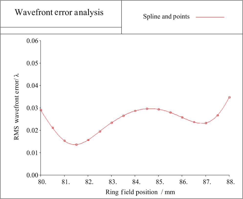
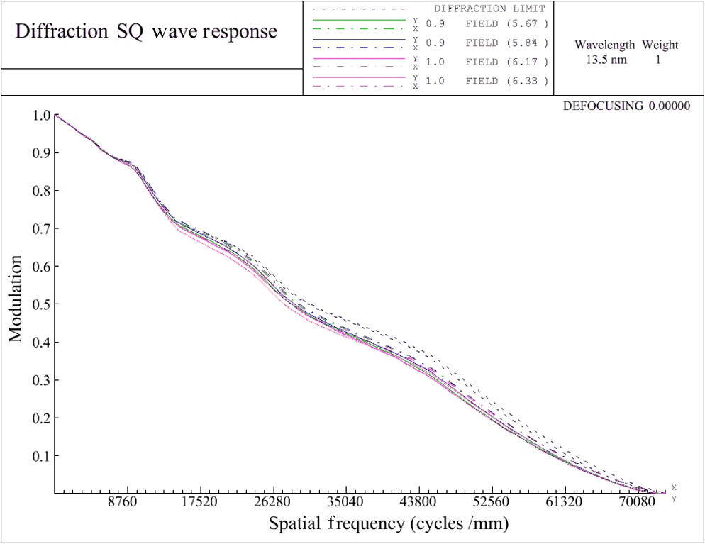
This reduction design has a CA of 6 deg, which is advantageous for compatibility with the reflective mask. However, a quarter separation of the exposure field is required to fit a 6 in. mask. In a -ring field at the wafer, the objective system has a composite RMS wavefront error of () and the distortion is corrected to better than 0.7 nm. The RMS wavefront error versus the ring field position is shown in Fig. 7. The size of obscuration is smaller than 30% of the radius of the pupil, which ensures a sufficient through-pitch behavior of the objective. The modulation transfer function (MTF) is shown in Fig. 8 and it shows that the image quality is close to the diffraction limitation. The resolution of an EUV lithographic system depends on the NA and resolution enhancement technologies. Combined with resolution enhancement technologies such as off-axis illumination and optical proximity correction,13 this six-mirror objective with an NA of 0.5 could provide a potential solution for 11-nm node EUV lithography.2,3 5.Other SolutionsThe grouping design method has the ability to generate new design forms. Resetting the initial system parameters (such as the NA and reduction) and the dependent variables in G1 and G3, the new design forms for G1 and G3 can be acquired. The design form of G2 will be changed accordingly to connect the ray paths of the new G1 and G3. Connecting the three groups, a new initial configuration will be generated. With the grouping design method, we present another two design forms for an 11-nm EUV projection objective. One of the design forms has a reduction of 4, and its layout is shown in Fig. 9. This reduction design has an NA of 0.41 and a full field size of at the wafer; accordingly the size of the mask is , which fits with a 6-in. mask and a single exposure. The CA of this design is 7.5 deg and the mask effects should be carefully taken into consideration. The reduction design has an NA of 0.45 and a CA of 7.0 deg. To fit the 6-in. mask, the half-field size at the wafer can be set to and twice the exposure is needed. The layout of the reduction design is shown in Fig. 10. All the potential solutions mentioned in this paper are summarized in Table 3. Table 3Solutions for high-NA projection objective.
All the three options for the projection objective have a central obscuration and could match a 6-in. mask. From a throughput point of view, the design has a full-field scan and the highest efficiency. However, the design has the largest NA and it would be advantageous from a mask-effects point of view. The design is a compromised solution in terms of NA, field size, and mask effects. 6.ConclusionIn this paper, a grouping design method with real ray tracing was extended to the design of an objective system with obscuration. Grouping design allocated the complexity of designing a whole system to each of the mirror groups. Real ray analysis was used instead of paraxial analysis, which avoids the discrepancy of the ray path induced by paraxial approximation. To control the size of pupil obscuration, the ratio of obscuration on the last folding mirror (M5) and exit mirror (M6) was taken as a design constraint of the image-side group, which enables a sufficient through-pitch behavior of the optics. Three specific design forms for 11-nm EUV projection objectives were presented and the performance of the design was analyzed in detail. The result shows that the grouping design method provides an effective approach to obtain high-NA EUV objective systems with obscuration. Designing this type of objective system provides potential solutions for an 11-nm node EUV lithography. ReferencesP. A. Kearneyet al.,
“Driving the industry towards a consensus on high numerical aperture extreme ultraviolet,”
Proc. SPIE, 9048 90481O
(2014). http://dx.doi.org/10.1117/12.2048397 PSISDG 0277-786X Google Scholar
M. Lowischet al.,
“Optics for EUV production,”
Proc. SPIE, 7636 763603
(2010). http://dx.doi.org/10.1117/12.848624 PSISDG 0277-786X Google Scholar
M. Lowischet al.,
“Optics for ASML’s NXE: 3300B platform,”
Proc. SPIE, 8679 86791H
(2013). http://dx.doi.org/10.1117/12.2012158 PSISDG 0277-786X Google Scholar
F. LiuY. Li,
“Design of multi-mirror optics for industrial extreme ultraviolet lithography,”
Opt. Rev., 20
(2), 121
–126
(2013). http://dx.doi.org/10.1007/s10043-013-0017-2 1340-6000 Google Scholar
F. LiuY. Li,
“Grouping design of eight-mirror projection objective for high-numerical aperture EUV lithography,”
Appl. Opt., 52
(29), 7137
–7144
(2013). http://dx.doi.org/10.1364/AO.52.007137 APOPAI 0003-6935 Google Scholar
Z. CaoY. LiF. Liu,
“Grouping design method with real ray tracing model for extreme ultraviolet lithographic objective,”
Opt. Eng., 52
(12), 125102
(2013). http://dx.doi.org/10.1117/1.OE.52.12.125102 OPEGAR 0091-3286 Google Scholar
R. Peeterset al.,
“ASML’s NXE platform performance and volume introduction,”
Proc. SPIE, 8679 86791F
(2013). http://dx.doi.org/10.1117/12.2010932 PSISDG 0277-786X Google Scholar
Z. CaoY. LiF. Liu,
“Manufacturable design of 16–22 nm extreme ultraviolet lithographic objective,”
Acta Opt. Sin., 33
(9), 0922005
(2013). http://dx.doi.org/10.3788/AOS GUXUDC 0253-2239 Google Scholar
J. T. Neumannet al.,
“Interactions of 3D mask effects and NA in EUV lithography,”
Proc. SPIE, 8522 852211
(2012). http://dx.doi.org/10.1117/12.2009117 PSISDG 0277-786X Google Scholar
M. F. BalM. SinghJ. J. M. Braat,
“Optimization of multilayer reflectors for extreme ultraviolet lithography,”
J. Microlith. Microfab. Microsyst., 3
(4), 537
–544
(2004). http://dx.doi.org/10.1117/1.1793171 Google Scholar
M. F. BalF. BociortJ. J. M. Braat,
“Designing extreme ultraviolet projection systems without obstruction and with multilayers,”
in Proc. OSA/IODCIMD,
IMD2
(2002). Google Scholar
R. Peeterset al.,
“EUV lithography: NXE platform performance overview,”
Proc. SPIE, 9048 90481J
(2014). http://dx.doi.org/10.1117/12.2046909 PSISDG 0277-786X Google Scholar
BiographyZhen Cao received his BS degree in optoelectronic information engineering from Xi’an Technological University in 2008. Currently, he is a PhD candidate directed by Professor Yanqiu Li in the School of Optoelectronics at Beijing institute of Technology. His current interests include optical system design and tolerance analysis for extreme ultraviolet lithography. Yanqiu Li received her MS and PhD degrees in optics from Harbin Institute of Technology of China. She worked as a senior engineer at Nikon, as an invited professor of Tohoku University of Japan, and as a frontier researcher at RIKEN of Japan. Currently, she is a professor at the School of Optoelectronics at Beijing institute of Technology, Beijing, China. She holds over 30 Chinese patents and has published numerous articles on lithographic science. |
||||||||||||||||||||||||||||||||||||||||||||||||||||||||||||||||||||||||||||||||||||||||||||||||||||||||||||||||||||||||||||||||||||||||||||||||||||||||||||||||