|
|
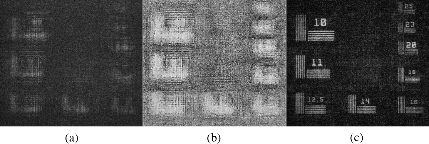
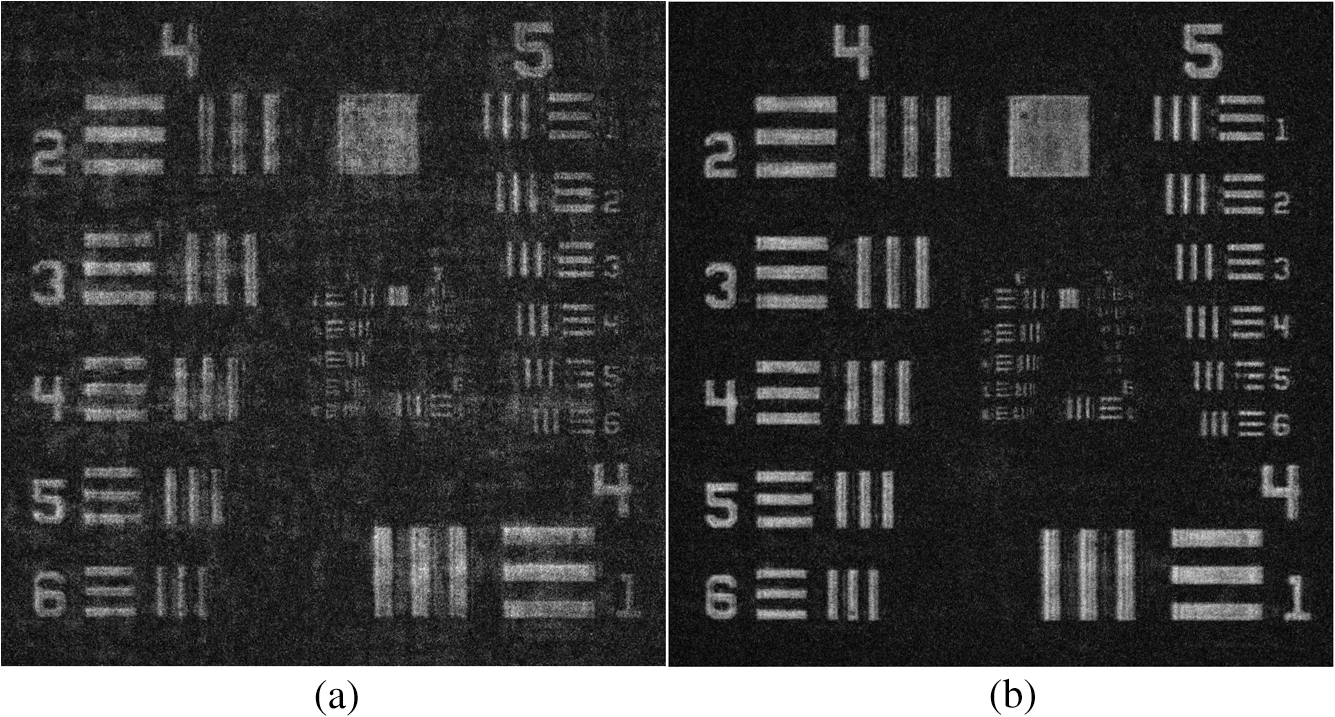
1.IntroductionThe developments of spatial light modulators (SLMs), especially those made of liquid crystal on silicon (LCoS), during the last four decades have boosted the development of computerized holography. The world of computerized holograms is roughly divided into two main types of holograms: computer-generated holograms (CGHs)1 and digital holograms (DHs).2 In general, SLMs are used as an interface between the electronic and optical domains and are, therefore, highly important for these two types of holograms. Usually, a CGH is referred to as a hologram that is synthesized in the computer from a virtual object and that is reconstructed optically by illuminating it with a light source of a certain type (e.g., a laser). A DH, in contrast, is considered in most of the professional literature as a hologram that is synthesized optically, usually by interfering light beams, and that is reconstructed digitally in the computer. SLMs are commonly integrated in various systems with both hologram types, CGH and DH. For the purposes of dynamic beam shaping and image formation, SLMs have been used as holographic displays for CGHs.3,4 SLMs were also used to synthesize CGHs by iterative algorithms,5,6 in which the CGH of the current iteration (i.e., the ’th version of the CGH) is displayed on an SLM, optically reconstructed, captured by the computer, compared with an ideal image and accordingly, the next () corrected version of the CGH is generated and displayed on the same SLM for the following iteration. However, CGHs, in general, and CGHs displayed on SLMs, in particular, are out of the scope of the present article, which deals with only a certain class of incoherent SLM-aided DH. SLMs have been used in different ways within DH systems. There are many examples of using an SLM as a display for the input data in the object channel of an interferometric hologram recorder,7,8 whereas the reference beam in these interferometers usually does not carry any spatial information. However, there are cases where an SLM also appears in the reference channel as an address selector,9,10 or as a phase-shifting device in a setup of an in-line digital holographic recorder for the purpose of removing the twin image and the bias term from the recorded hologram.11,12 Besides the usage for phase shifting, the SLM can be used as a beam splitter between the reference and the object beams and as a diffractive lens for controlling the location of the beam focuses.13,14 Other tasks for SLMs in DH systems are discussed in the following sections. In this review, we survey recent SLM-aided digital holography systems in whose development our group has taken part. The following section is devoted to the Fresnel incoherent correlation holography (FINCH) system, in which an SLM is simultaneously used for several purposes. Lately, the concept of FINCH has been extended for imagers with a synthetic aperture, termed synthetic aperture with Fresnel elements (SAFE). The topic of SAFE is reviewed in Sec. 3. 2.Fresnel Incoherent Correlation HolographyThe FINCH system was introduced in 2007.15 Since then, FINCH and other conceptually related systems have been widely investigated by many research groups.16–38 Several features of FINCH may explain this high interest, including its relative simplicity, its single channel common-path configuration, and its capability of recording the entire three-dimensional (3-D) information of spatially incoherently illuminated targets. The FINCH-based fluorescence microscope (FINCHSCOPE)17 and its recent efficient version,34 which is based on a liquid crystal gradient index lens, are essential developments of FINCH. An interesting scheme for achieving a wide field-of-view in a FINCH-like system, accomplished using an optical relay system positioned between the microscope’s objective lens and the SLM, is presented in Ref. 29. Another notable method, also based on the working concept of FINCH, but without any SLMs, is the self-interference incoherent digital holography (SIDH).39,40 In SIDH, two mirrors of different spherical curvatures are incorporated into a modified Michelson interferometer that replaces the single-channel design of FINCH. Other tasks, besides holographic imaging, have been successfully demonstrated including an anisotropic edge contrast enhancement of 3-D objects, achieved by displaying special phase patterns on the SLM in order to create a point-spread function with a vortex structure.41 An accurate axial localization of the point-like objects has been accomplished by the same group using digital processing performed on a FINCH-like hologram.42 It is out of the scope of this article to present every variation and application of FINCH or its closed systems. We mainly review, in this section, several SLM-related structural developments of FINCH. 2.1.Initial and Early DesignsA schematic representation of the earliest design of FINCH15 is given in Fig. 1. A core component of FINCH is a phase-only LCoS-SLM that is simultaneously used as a diffractive lens and as a beam splitter, thereby forming a single-channel system. The system description starts with the assumption that spatially incoherent light is scattered by, or emitted from, a 3-D target. The light is collected by the objective lens and is later modulated by a phase-only SLM so that each spherical beam that originates from a single point of the object is split into two spherical beams with different wavefront curvatures. The two spherical beams interfere on the plane of the digital camera, forming a Fresnel hologram of the object point. The recorded hologram is a summation over the intensity contributions from all source points since the object is spatially incoherent. It is now apparent why FINCH is considered an incoherent, single-channel interferometer. The requirement to produce two different spherical beams from each object point is achieved by rendering two diffractive lenses using the SLM, each of which occupies a randomly selected half of all SLM pixels. Therefore, whenever a wave from an object point is introduced into the SLM, two spherical waves are returned from the SLM. The final resulting interference pattern is actually the Fresnel hologram of the observed 3-D object. From it, the recorded 3-D target can be reconstructed onto a desired far plane using a conventional digital process denoted as numerical Fresnel backpropagation.43 Fig. 1Schematic of the first Fresnel incoherent correlation holography (FINCH) recorder:15 BS, beam splitter; BPF, band-pass filter; , objective lens; SLM, spatial light modulator; CCD, charge-coupled device. 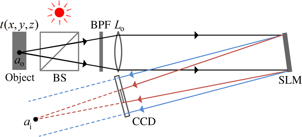 A Fresnel hologram captured by FINCH contains, like many other on-axis holograms, three terms: one is a relatively high constant term and the other two terms, a complex conjugate pair, are a convolution between the object intensity and a -dependent quadratic phase function. Due to this well-known twin-image problem,43 it is almost impossible to properly extract the 3-D image of the object by a direct reconstruction of the hologram, as mutual disturbances between the above mentioned terms exist. By using a process known as phase shifting, two of the above three terms can be eliminated so that a single desired convolution term is obtained. In this process, three holograms of the same object are recorded. The holograms differ from each other as each one is recorded with a different phase constant that multiplies only one of the two diffractive lenses displayed on the SLM. Hence, in addition to the two tasks of splitting and focusing beams in FINCH, a third mission of a phase shifter is added to the same SLM. The final hologram is digitally formed as a superposition of the three raw holograms. This complex-valued final hologram yields only the desired single convolution between the object and a -dependent quadratic phase function. The numerical reconstruction of the final hologram produces a 3-D image of the object, without any disruptions from other holographic terms. The initial configuration of FINCH was investigated in various studies for different applications. The first FINCH was demonstrated with white-light reflecting objects,15 while a few months later, FINCH was applied for fluorescence objects of various colors.16 Later, a FINCHSCOPE was demonstrated with biological specimens.17 For demonstration purposes, results from a FINCH system built according to the early design of Fig. 1, but using a transmissive rather than a reflective resolution object, are shown in Fig. 2. The magnitude and phase of the superposed hologram are presented in Figs. 2(a) and 2(b), respectively. The reconstructed image of the transmissive resolution chart is shown in Fig. 2(c), clearly revealing many of its details. Nevertheless, these early FINCH systems were not optimal in their performance due to three main aspects. First, the way of multiplexing two diffractive lenses on a single SLM, by allocating different pixels for the two lenses, has become a main source of noise on the reconstruction plane. Second, some of the system parameters were selected arbitrarily, without proper understanding of their influence on the various system performances. Finally, reducing the optical path difference (OPD) in FINCH, for processing wide-bandwidth light sources, was done by inefficiently increasing the length of the systems. These difficulties were fruitfully solved in the later versions of FINCH;19,21,24 some of them are reviewed in Sec. 2.2. 2.2.Element Multiplexing using the Polarization MethodThe use of an SLM enables the realization of FINCH as a single-channel interferometer. This has several benefits, but requires multiplexing two diffractive lenses on a single phase-only SLM. This is not trivial since two phase functions are summed to a function, which is not necessarily a pure phase. Hence, the resulting complex function cannot be displayed directly on phase-only SLMs. The initial multiplexing method was based on spatial multiplexing as the two phase functions of the diffractive elements were simply displayed on different pixels of the SLM. Subsequently, the two diffractive elements were fragmented, leading to an apparent noise on the reconstructed image. The polarization method described in the following is an efficient method to eliminate this noise. Some of the commercially available LCoS-SLMs are electronically controllable birefringent devices that only modulate light coming with a certain linear polarization orientation. This characteristic can be exploited for the task of multiplexing two elements on a single SLM. As the SLM is sensitive to a specific polarization orientation, one component of the electric field vector can be used as a wave modulated with the desired diffractive lens, while the other orthogonal component, which is not affected by the SLM, can be used as a wave without any modulation. Therefore, in the polarization method of multiplexing diffractive elements, the diffractive lens occupies the complete aperture of the system, thus, the SLM-realized elements (i.e., a diffractive lens and a clear aperture) are continuous over the entire optical aperture. A comprehensive description of the polarization method of element multiplexing in FINCH is provided in Ref. 19. Here, it is reviewed with the help of Fig. 3, showing a FINCH system with an extra glass lens .21,24 An object point, positioned at a working distance from the objective lens , emits a spherical beam which is introduced into the system. An input polarizer, , oriented at an angle of 45 deg to the SLM active axis, allows the operation of two different imaging systems in the same physical single-channel setup. Only the beam polarization component parallel to the SLM active axis is converged by the diffractive lens. The orthogonal polarization component is not affected by the SLM at all. Hence, each of the two simultaneous imaging systems operates with one of two orthogonal polarization beams. For both imagers, the input beam is collected by the objective lens and is then focused to two different image points, at , for the imager in which the SLM-displayed diffractive lens is effective, and at , for the imager in which the SLM does not affect the beam. A digital camera, located between the two image points, records the interference pattern between a spherical beam converging toward and a spherical beam diverging from . The output polarizer, , usually oriented at an angle of 45 deg, projects the two orthogonal polarization components onto a common orientation in order to enable interference between the beams. The hologram digital reconstruction procedure is identical to the process done with the early FINCH versions mentioned above. Fig. 3Schematic of a FINCH recorder in the polarization method: and , polarizers; , objective lens; , converging lens; SLM, spatial light modulator; CCD, charge-coupled device. The circled black dot, up arrow, and up arrow with circled black dot represent polarization directions, perpendicular, parallel and 45 deg with respect to the plane of the page, respectively. Figure adapted from Ref. 44. 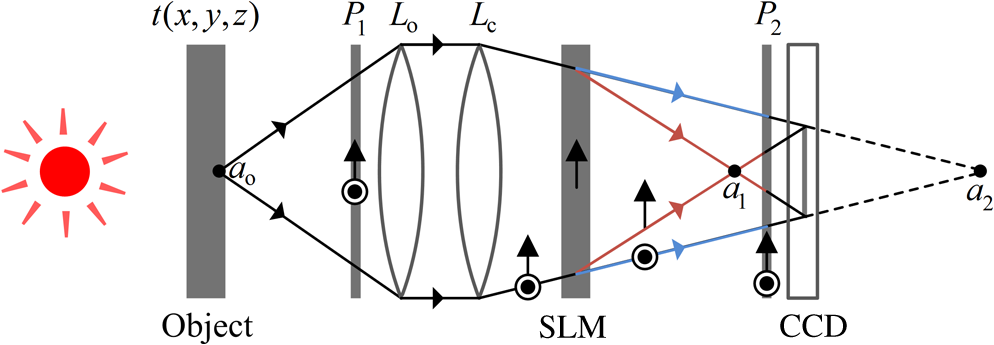 In order to demonstrate the advantage of the polarization method of element multiplexing19 over the previously described spatial multiplexing method,15 a FINCH system based on the schematic of Fig. 3 was built. The distance between the SLM and the camera was set to 40 cm, and a diffractive lens with a focal length of 28 cm was displayed on the SLM. A United States Air Force (USAF) resolution chart served as a test target and holograms were recorded using both multiplexing methods. The results are summarized in Fig. 4. In the spatial multiplexing experiment, three holograms were acquired with the input and output polarizers set in parallel to the SLM active axis. Fifty percent of the SLM pixels were set to a constant phase. The target reconstruction results for this method are presented in Fig. 4(a). In the polarization multiplexing method experiment, the three holograms were recorded with the polarizers set at 45 deg to the SLM active axis, and all SLM pixels were allocated for the diffractive lens. The target reconstruction results for this method are presented in Fig. 4(b). Obviously, the advantage of the polarization method over the earlier method is demonstrated. 2.3.Confocal Fresnel Incoherent Correlation HolographySixty years ago, Minsky45 presented the foundations of confocal microscopy. Since then, his ideas have been integrated to incoherent46,47 and coherent48–50 holography. A main virtue of confocal microscopy is its ability to perform optical sectioning. This is in contrast to ordinary microscopy, where the quality of the in-focus parts of a specimen may be faded by images of out-of-focus parts. Usually, this deterioration is elevated when examining thick specimens. Minsky’s confocal microscope combines two measures to solve this image quality deterioration problem: one, selective illumination of the object point of interest and two, near complete blockage of light from out-of-focus object points using an opaque screen, whereas light from the point of interest freely goes to the detector through a pinhole. This solution requires a scanning procedure in order to image an entire specimen. Last year, a motionless, SLM-aided, confocal setup of FINCH was presented44 as a new sectioning method and as an answer to the problem of the relatively low axial resolution of conventional FINCH.51 Several months after the appearance of the first confocal FINCH,44 another confocal microscope was proposed, combining standard FINCH with a spinning disk.52 However, note that the original confocal FINCH44 is motionless and accomplishes optical sectioning of the observed specimen without losing the inherent transverse super-resolution capabilities of the original FINCH.21 Therefore, confocal FINCH can image different planes of interest at various depths while blocking light from other planes. By that, the axial imaging resolution of the imager is enhanced and small details that otherwise would be lost are discovered. The incorporation of the optical sectioning feature into FINCH has been achieved by using an unusual optical element dubbed a phase pinhole. The phase pinhole is an SLM implemented element that enables the creation of a FINCH hologram of only a particular object point out of the entire observed scene. The scheme of the confocal FINCH shown in Fig. 5 is based on the dual lens FINCH design (Fig. 3) with an added phase-only SLM, , located at the plane of the first image point . is actually used to implement the phase pinhole in the system. A diffractive optical element, consisting of a diverging axicon that surrounds a small circular area of uniform phase modulation is displayed on . For every scanning point , the phase-shifting procedure is implemented at the pinhole region by setting three different phases for the three captured holograms, whereas on the same diffractive lens is displayed during the acquisition of every object section. Since the phase is altered only within the phase pinhole, any optical pattern on , outside the phase pinhole, is vanished following the phase-shifting process. Therefore, the phase pinhole can be considered as an absorbing pinhole for the polarization components parallel to the active axis and as an open aperture for the orthogonal polarization components. Because of the phase shifting and due to the incoherence nature of the light source, the only information left in the computer is the interference pattern between light that passes through the phase pinhole and its orthogonal counterparts imaged at the point . Fig. 5Schematic of a confocal FINCH recorder: and , polarizers; , objective lens; , converging lens; and , spatial light modulators; CCD, charge-coupled device. Figure adapted from Ref. 44.  The integration of the phase pinhole into FINCH is appropriate for realizing optical sectioning. Nevertheless, improved sectioning results can be accomplished using a complete confocal FINCH (shown in Fig. 5) through the incorporation of a point illumination setup. None of the target points located outside the cone of the illumination are detected by the camera. Thus, there are two mechanisms operating together to enable optical sectioning, namely, the phase pinhole and the point illumination. Clearly, since only a single object point is well imaged, a scanning procedure is required to capture the whole object. Fortunately, scanning of the entire object can be performed without any mechanical movements by electronically shifting the phase pinhole onto different pixels of .44 In the sectioning experiments, results of a conventional FINCH (Fig. 3) were compared to an optical sectioning FINCH (as shown in Fig. 5, but without the point illumination, so that the role of the phase pinhole is highlighted). The phase pinhole is considered as the more innovative part in the system, as scanning illumination systems are regularly utilized in other confocal microscopes.48–50 It should be noted that sectioning accomplished only by the phase pinhole can be suitable for imaging tasks in which the observed scene cannot be selectively illuminated. The experimental results are summarized in Fig. 6. Reconstructions from conventional FINCH holograms of two resolution charts, closest to the objective and farthest from it, are shown in Figs. 6(a) and 6(b), respectively. It is clear that the images of the out-of-focus targets greatly diminish the quality of the reconstruction. Actually, the image of the farthest target is hardly seen in Fig. 6(b), although this target with the digits “18.0” is actually in focus. The reconstructed images of the sectioning FINCH equivalents of Figs. 6(a) and 6(b) are shown in Figs. 6(c) and 6(d), respectively. Here, the images of the out-of-focus objects are severely diminished so that the images of the in-focus objects are clearly seen with better contrast, complete details, and weak background noise. The optical sectioning capability of the proposed system is thus demonstrated and is expected to be improved even further once the point illumination is incorporated. The confocal FINCH can well suppress out-of-focus images from a FINCH hologram, combining the high-lateral resolution capabilities of FINCH and the optical sectioning capabilities of confocal microscopy. Fig. 6Experimental results: (a) and (b) FINCH reconstructions of and resolution charts located 30 and 31 cm away from the objective lens, respectively; (c) and (d) are the optical-sectioning-FINCH equivalents of (a) and (b), respectively. Figure partially adapted from Ref. 44. 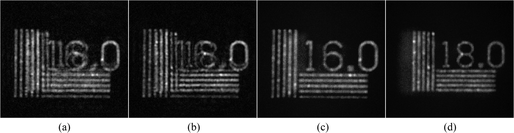 3.Synthetic Aperture with Fresnel ElementsThe resolving power of a diffraction-limited imaging system is related to the light wavelength () and the numerical aperture (NA) of the system.53 Specifically, the spatial resolution of an imaging system is proportional to, and is limited by, the ratio of these two properties, . Techniques to overcome the diffraction limit have been suggested and studied by many researchers.54–61 Synthetic aperture (SA) imaging is a well-researched approach to improve the resolving capabilities of an imaging system. In SA imaging, for a set distance between the observed target and the imager, the effective aperture of a system is synthetically extended, leading to an increased NA. Consequently, this extension enables the system to resolve finer details of an observed target. A common approach to SA implementation using a holography system (of a finite physical aperture) is to capture several interference patterns from various points of view. The interference patterns are later tiled together into a new larger interference pattern. This pattern can be considered as being acquired by a virtual imager of an effective aperture that is wider than the actual physical aperture, and thus of a higher NA.56–61 In this sense, SA is considered as a super-resolution method, since it increases the resolving power beyond the resolution limit of a single-finite aperture of the physical system. It is not surprising that techniques of holographic imaging are frequently used for implementing SA.57–60 In general, holographic SA imaging is possible since each hologram, which serves as an element of the SA mosaic, also contains the phase information. This information is an essential quantity, enabling a successful SA implementation. In other words, by accurately recording the complex amplitude of the electromagnetic field on the system aperture plane, containing both the magnitude and phase distributions, an SA hologram can be composed. Holographic techniques are typically demonstrated with coherent laser illumination. The work of Granero et al.,60 in which super-resolution microscopy using digital Fourier holograms is achieved using tilted laser beams, is an example of holographic SA. However, certain targets cannot be illuminated by lasers or coherently imaged; there are cases in which the targets themselves radiate incoherent light. Thus, the ability to synthesize an aperture under incoherent illumination is important. Indebetouw et al.58 presented an incoherent scanning holography SA system. Still, in this case, the target is illuminated using an interference pattern obtained from two coherent beams that originate from the same laser. Recently, a laser-free SA imager for incoherently illuminated objects, SAFE, has been proposed.62 This method is based on FINCH in the sense that each element in the SA mosaic is actually acquired using a modified FINCH system. In general, the SA in SAFE is formed by combining several Fresnel subholograms recorded from various viewpoints by a limited aperture FINCH recorder. Since its first demonstration, SAFE has evolved in parallel to FINCH, such that every improvement in FINCH has been later adapted to SAFE.62–64 The latest and best performing SAFE configuration, dubbed dual lens SAFE,64 is reviewed in Sec. 3.1. 3.1.Dual Lens Synthetic Aperture with Fresnel ElementsThe dual lens SAFE system, presented in Fig. 7, is based on the dual lens FINCH system (Fig. 3). In both systems, the wave emitted from each object point is split into two closely spaced spherical waves with different curve radii, which are interfered on the camera plane. Similar to FINCH, in order to achieve optimal resolution, the system is configured to fulfill the requirement of a perfect overlap between the two interfering waves on the camera plane.21 The advantage of working with two spherical waves, rather than with one spherical wave and one plane wave, is manifested by the system (either FINCH or SAFE) capability of handling light of a wider bandwidth, while keeping the visibility of the recorded interference patterns sufficient. This is because the maximal OPD between two interfering waves becomes shorter as the two image points, generated by focusing the two spherical waves, get closer to each other.24 Fig. 7A schematic configuration of the dual lens synthetic aperture with Fresnel elements (SAFE) concept. In (a), a continuous central holographic element using the dual lens FINCH method is recorded. In (b), a marginal holographic element is recorded. The two SLMs, and , are shifted in two symmetrical viewpoints in front of the collimation lens . Two diffractive lenses, with focal lengths and , are displayed on and , respectively. In (c), a marginal holographic element symmetrical to that of (b) is recorded by switching the two diffractive lenses and . and , lenses; and , polarizers; and , spatial light modulators; CCD, charged-coupled device. 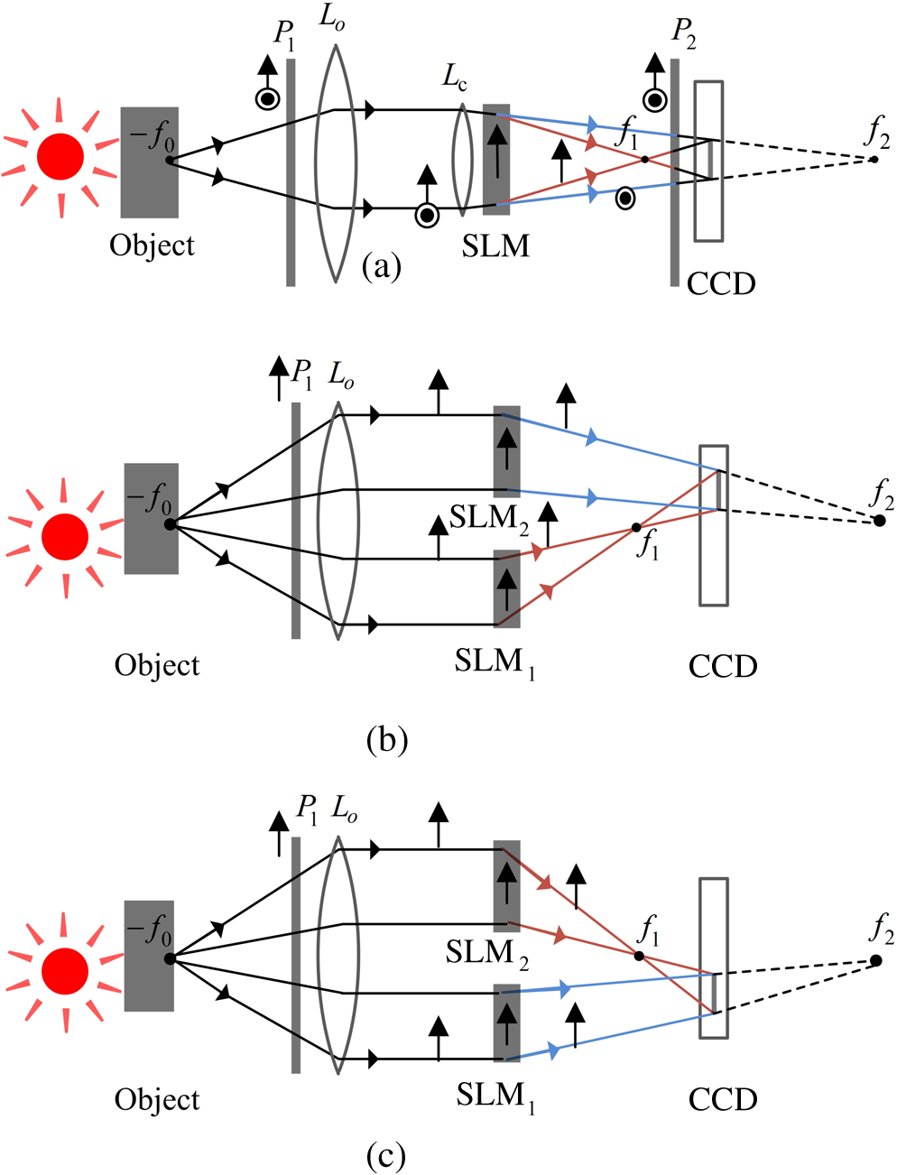 Another characteristic feature of the dual lens SAFE,64 in contrast to its previous iterations, is that the recorded subholograms are not stitched together along the central , axes of the final mosaic hologram. This guideline yields better results because most of the energy emitted from commonly observed objects propagate toward the system in a relatively small angle, thus, any stitch between subholograms that passes through the central area (where most of the light concentrates) might distort the reconstructed image. Hence, a continuous central subhologram is first recorded by a conventional dual lens FINCH system. In Fig. 7(a), the recording process of the central subhologram is schematically described. Two spherical waves that originate from the same object point converge to the distances and from the SLM. A resulting interference pattern encodes the object point position in space. Note that the lens collimates the spherical wave emitted from the object point into a plane wave. SAFE is designed as a telescopic holography system for imaging objects located at infinity. As such, is considered here as an external element to the system that is used to simulate very far illuminating objects. As previously mentioned, two polarizers, and , positioned before and after the SLM, respectively, are oriented at 45-deg angles with respect to the SLM active axis, in order to achieve maximum visibility of the interference pattern between the two waves. The refractive lens converts the plane wave obtained from into a converging spherical wave. This wave is split into two spherical waves by the SLM. Optimal resolution is achieved when the two waves perfectly overlap on the camera plane. In a dual lens FINCH, this condition is fulfilled by setting the distance between the SLM and the camera plane to be .21 Following the first stage of recording the central subhologram, two SLMs, denoted and , are symmetrically shifted in opposite directions away from the optical axis [Figs. 7(b) and 7(c)]. Two different regions of the wave emitted from the object point are directed by the two SLMs to interfere on the camera plane, enabling an additional noncentral subhologram to be recorded. The diffractive elements that create the two interfering waves are composed of two different segments of two quadratic phase functions, one with a focal length and another with a focal length , displayed on and , respectively. Note that the lens is no longer necessary, due to the physical separation between the interfering waves for the noncentral subholograms, as opposed to the central subhologram in which lens multiplexing (using the polarization method) is used. Additionally, in order to achieve maximal power efficiency at the noncentral subholograms, the exit polarizer is removed, whereas the entrance polarizer is adjusted to the same orientation of the active axes of the SLMs. By switching the two masks that are displayed on the SLMs, while keeping and at their designated locations, a Fresnel holographic element on the opposite and symmetrical side of the optical axis is recorded [Fig. 7(c)]. Thus, electronic switching enables to cut down the amount of physical repositioning of the SLMs in the SA recording process. The following presented experiment64 with a dual lens SAFE system demonstrates the resolution improvement that can be achieved with this imager. In the experiment, the various SLMs, shown in Fig. 7, were realized as different apertures on the same large LC board. The image presented in Fig. 8(a) was produced by a conventional (nonholographic) imaging system. This system and the FINCH system, shown in Fig. 7(a), have similar NAs. The line grids along both axes in the resolution chart are not perceived in Fig. 8(a), due to the insufficient resolving power of the imager. The physical aperture in this case is not large enough. In Figs. 8(b) and 8(c), the intensities along horizontal and vertical cross-sections do not reveal the existence of any gratings. Fig. 8Experimental results obtained by recording a section of a resolution chart: (a) the image obtained by the conventional imaging system; (b) and (c) the intensity cross-section of (a) along the horizontal and vertical dashed red lines, respectively; (d) the reconstructed image corresponding to the hologram produced by a FINCH system; (e) and (f) the intensity cross-section of (d) along the horizontal and vertical dashed red lines, respectively; (g) the reconstructed image corresponding to the hologram produced by dual lens SAFE; (h) and (i) the intensity cross-section of (g) along the horizontal and vertical dashed red lines, respectively; (j) the reconstructed image corresponding to the hologram produced by a FINCH system; (k) and (l) the intensity cross-section of (j) along the horizontal and vertical dashed red lines, respectively. Figure adapted from Ref. 64. 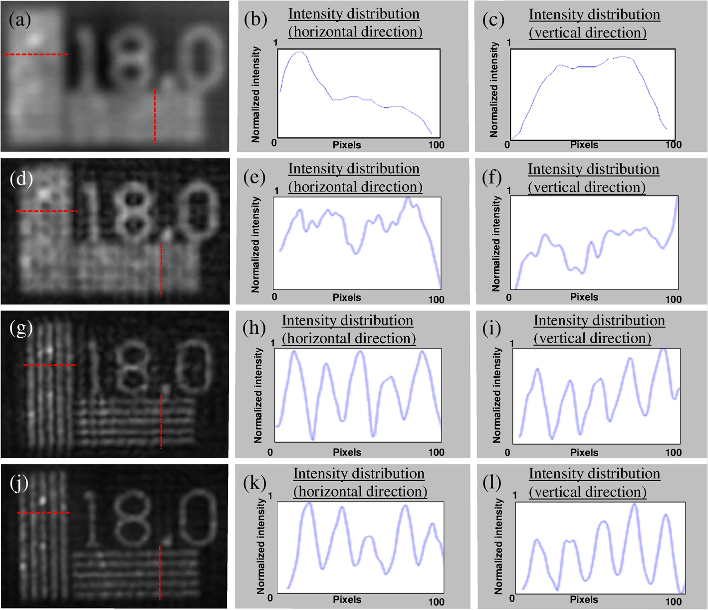 The resolving power of FINCH, as previously shown,21 can exceed the resolving power of a regular incoherent imaging system of a similar NA. In Fig. 8(d), a reconstructed image of the target, produced by a dual lens FINCH setup of equivalent NA as the imager used for Fig. 8(a), is shown. Indeed, there is a perceivable difference between the systems as the digits are more clearly seen. Still, the horizontal and vertical lines are not clearly resolved [Figs. 8(e) and 8(f), respectively]. The mosaic SA hologram reconstructed image of the resolution target, obtained using the proposed dual lens SAFE system, is shown in Fig. 8(g). Notice how the vertical and horizontal lines are clearly revealed in this figure and in the presented cross-sections in Figs. 8(h) and 8(i). Without doubt, there is a significant increase in sharpness and visibility. For a comparison, Fig. 8(j) presents an image of the target, reconstructed from a hologram that was recorded using a dual lens FINCH system with a physical NA that is similar to the effective NA of the SAFE configuration. Fewer artifacts are present in this figure, which may be attributed to the continuity of the produced hologram, contrary to the dual lens SAFE method, which contains discontinuities in the mosaic hologram. The similarities in the cross-sections [Figs. 8(k) and 8(l) versus Figs. 8(h) and 8(i)] indicate that in both of these systems, the ability to transfer the higher frequencies of an object is similar. 4.ConclusionsSeveral incoherent hologram recorders have been reviewed in this article from the perspective of using phase-only SLMs. In general, because of the SLM, FINCH and its daughter systems are configured as single channel on-axis hologram recorders. In addition, SLMs are effective for implementing digitally controllable optical diffractive elements, phase shifters for the phase shifting procedure and phase pinholes for image sectioning. After using SLMs in many ways along many years, we can testify that this technology has many benefits making the hologram recorders flexible, easy to use, relatively fast, and robust. However, incoherent hologram recorders, in general, and SLM-aided systems, in particular, have some drawbacks as well, presenting a challenge for further research. Among the drawbacks, we should mention that the improvement of lateral resolution in FINCH is compromised with some reduction of the axial resolution, as is lengthily discussed in Ref. 51. Another problem is that the diffractive dispersion of SLM displayed lenses limits the spectral bandwidth of the light which can be utilized in the SLM-aided systems. A common weakness of incoherent hologram recorders is their inability to image phase objects, as is well practiced in coherent holography. The coherent systems, on the other hand, cannot handle self-illuminating objects, as is easily done in incoherent holography. Finally, a technological disadvantage of the existing phase-only SLMs is their reflective mode of operation. In order to create power-efficient systems and to massively integrate SLMs in commercial holographic imagers, we believe that the industry should concentrate on the development of SLMs in transmission mode of operation. We hope that this review article will encourage the SLM industry to develop a high standard transmission phase-only SLM as soon as possible. AcknowledgmentsWe thank the persons with whom we had the honor to collaborate in the various works presented in this review paper. Especially, we wish to thank Gary Brooker, Barak Katz, and Nisan Siegel. This work was supported by The Israel Ministry of Science and Technology (MOST), by The Israel Science Foundation (ISF) (Grant No. 439/12) and by the National Institutes of Health (NIH), National Institute of General Medical Sciences Award Number U54GM105814. ReferencesW. H. Lee,
“Computer-generated holograms: techniques and applications,”
Prog. Opt., 16 121
–232
(1978). POPTAN 0079-6638 Google Scholar
U. Schnars and W. Jueptner, Digital Holography, 1st ed.Springer, Berlin
(2005). Google Scholar
F. Mok et al.,
“Real-time computer-generated hologram by means of liquid-crystal television spatial light modulator,”
Opt. Lett., 11
(11), 748
–750
(1986). http://dx.doi.org/10.1364/OL.11.000748 OPLEDP 0146-9592 Google Scholar
J. N. Mait and G. S. Himes,
“Computer-generated holograms by means of a magnetooptic spatial light modulator,”
Appl. Opt., 28
(22), 4879
–4887
(1989). http://dx.doi.org/10.1364/AO.28.004879 APOPAI 0003-6935 Google Scholar
U. Mahlab, J. Rosen and J. Shamir,
“Iterative generation of holograms on spatial light modulator,”
Opt. Lett., 15 556
–558
(1990). http://dx.doi.org/10.1364/OL.15.000556 OPLEDP 0146-9592 Google Scholar
J. Rosen et al.,
“Electro-optic hologram generation on spatial light modulators,”
J. Opt. Soc. Am. A, 9
(7), 1159
–1166
(1992). http://dx.doi.org/10.1364/JOSAA.9.001159 JOAOD6 0740-3232 Google Scholar
K. Ueno and T. Saku,
“PLZT spatial light modulator for a 1-D hologram memory,”
Appl. Opt., 19 164
–172
(1980). http://dx.doi.org/10.1364/AO.19.000164 APOPAI 0003-6935 Google Scholar
J. F. Heanue, M. C. Bashaw and L. Hesselink,
“Volume holographic storage and retrieval of digital data,”
Science, 265
(5173), 749
–752
(1994). http://dx.doi.org/10.1126/science.265.5173.749 SCIEAS 0036-8075 Google Scholar
C. Denz et al.,
“Volume hologram multiplexing using a deterministic phase encoding method,”
Opt. Comm., 85
(2–3), 171
–176
(1991). http://dx.doi.org/10.1016/0030-4018(91)90389-U OPCOB8 0030-4018 Google Scholar
J. F. Heanue, M. C. Bashaw and L. Hesselink,
“Encrypted holographic data storage based on orthogonal-phase-code multiplexing,”
Appl. Opt., 34 6012
–6015
(1995). http://dx.doi.org/10.1364/AO.34.006012 APOPAI 0003-6935 Google Scholar
C.-S. Guo et al.,
“Phase-shifting with computer-generated holograms written on a spatial light modulator,”
Appl. Opt., 42
(35), 6975
–6979
(2003). http://dx.doi.org/10.1364/AO.42.006975 APOPAI 0003-6935 Google Scholar
V. Micó et al.,
“Phase-shifting Gabor holography,”
Opt. Lett., 34 1492
–1494
(2009). http://dx.doi.org/10.1364/OL.34.001492 OPLEDP 0146-9592 Google Scholar
Y. Rivenson et al.,
“Single channel in-line multi-modal digital holography,”
Opt. Lett., 38 4719
–4722
(2013). http://dx.doi.org/10.1364/OL.38.004719 OPLEDP 0146-9592 Google Scholar
R. Kelner, B. Katz and J. Rosen,
“Common path in-line holography using enhanced joint object reference digital interferometers,”
Opt. Express, 22 4995
–5009
(2014). http://dx.doi.org/10.1364/OE.22.004995 OPEXFF 1094-4087 Google Scholar
J. Rosen and G. Brooker,
“Digital spatially incoherent Fresnel holography,”
Opt. Lett., 32 912
–914
(2007). http://dx.doi.org/10.1364/OL.32.000912 OPLEDP 0146-9592 Google Scholar
J. Rosen and G. Brooker,
“Fluorescence incoherent color holography,”
Opt. Express, 15 2244
–2250
(2007). http://dx.doi.org/10.1364/OE.15.002244 OPEXFF 1094-4087 Google Scholar
J. Rosen and G. Brooker,
“Non-scanning motionless fluorescence three-dimensional holographic microscopy,”
Nat. Photonics, 2 190
–195
(2008). http://dx.doi.org/10.1038/nphoton.2007.300 Google Scholar
B. Katz, D. Wulich and J. Rosen,
“Optimal noise suppression in Fresnel incoherent correlation holography (FINCH) configured for maximum imaging resolution,”
Appl. Opt., 49 5757
–5763
(2010). http://dx.doi.org/10.1364/AO.49.005757 APOPAI 0003-6935 Google Scholar
G. Brooker et al.,
“Optimal resolution in Fresnel incoherent correlation holographic fluorescence microscopy,”
Opt. Express, 19 5047
–5062
(2011). http://dx.doi.org/10.1364/OE.19.005047 OPEXFF 1094-4087 Google Scholar
P. Bouchal et al.,
“Point spread function and two-point resolution in Fresnel incoherent correlation holography,”
Opt. Express, 19 15603
–15620
(2011). http://dx.doi.org/10.1364/OE.19.015603 OPEXFF 1094-4087 Google Scholar
J. Rosen, N. Siegel and G. Brooker,
“Theoretical and experimental demonstration of resolution beyond the Rayleigh limit by FINCH fluorescence microscopic imaging,”
Opt. Express, 19 26249
–26268
(2011). http://dx.doi.org/10.1364/OE.19.026249 OPEXFF 1094-4087 Google Scholar
Y. Tone et al.,
“Analysis of reconstruction characteristics in fluorescence digital holography,”
Digital Holography and Three-Dimensional Imaging, OSA Techinal Digest (CD), Optical Society of America, Washington DC
(2011). Google Scholar
X. Lai et al.,
“Fluorescence holography with improved signal-to-noise ratio by near image plane recording,”
Opt. Lett., 37 2445
–2447
(2012). http://dx.doi.org/10.1364/OL.37.002445 OPLEDP 0146-9592 Google Scholar
B. Katz et al.,
“Enhanced resolution and throughput of Fresnel incoherent correlation holography (FINCH) using dual diffractive lenses on a spatial light modulator (SLM),”
Opt. Express, 20 9109
–9121
(2012). http://dx.doi.org/10.1364/OE.20.009109 OPEXFF 1094-4087 Google Scholar
T. Man et al.,
“Quantitative evaluation of spatial phase light modulator characteristics in Fresnel incoherent correlation holography,”
Proc. SPIE, 8556 855613
(2012). http://dx.doi.org/10.1117/12.999661 PSISDG 0277-786X Google Scholar
H. Chen et al.,
“Effect of phase-shift step on hologram reconstruction in Fresnel incoherent correlation holography,”
Proc. SPIE, 8556 85560L
(2012). http://dx.doi.org/10.1117/12.999625 PSISDG 0277-786X Google Scholar
X. Lai and S. Zeng,
“Optical path difference characteristics of the fluorescence holographic system,”
Proc. SPIE, 8556 855617
(2012). http://dx.doi.org/10.1117/12.2001375 PSISDG 0277-786X Google Scholar
N. Siegel, J. Rosen and G. Brooker,
“Reconstruction of objects above and below the objective focal plane with dimensional fidelity by FINCH fluorescence microscopy,”
Opt. Express, 20 19822
–19835
(2012). http://dx.doi.org/10.1364/OE.20.019822 OPEXFF 1094-4087 Google Scholar
P. Bouchal and Z. Bouchal,
“Wide-field common-path incoherent correlation microscopy with a perfect overlapping of interfering beams,”
J. Eur. Opt. Soc. Rapid Publ., 8 13011
(2013). http://dx.doi.org/10.2971/jeos.2013.13011 Google Scholar
N. Siegel, J. Rosen and G. Brooker,
“Faithful reconstruction of digital holograms captured by FINCH using a Hamming window function in the Fresnel propagation,”
Opt. Lett., 38 3922
–3925
(2013). http://dx.doi.org/10.1364/OL.38.003922 OPLEDP 0146-9592 Google Scholar
X. Lai et al.,
“Violation of the Lagrange invariant in an optical imaging system,”
Opt. Lett., 38 1896
–1898
(2013). http://dx.doi.org/10.1364/OL.38.001896 OPLEDP 0146-9592 Google Scholar
P. Bouchal and Z. Bouchal,
“Concept of coherence aperture and pathways toward white light high-resolution correlation imaging,”
New J. Phys., 15 123002
(2013). http://dx.doi.org/10.1088/1367-2630/15/12/123002 NJOPFM 1367-2630 Google Scholar
K. Tsuchiya et al.,
“Influence of spatial coherence degree in fluorescence digital holography,”
in Conf. on Lasers and Electro-Optics Pacific Rim,
(2013). Google Scholar
G. Brooker et al.,
“In-line FINCH super resolution digital holographic fluorescence microscopy using a high efficiency transmission liquid crystal GRIN lens,”
Opt. Lett., 38 5264
–5267
(2013). http://dx.doi.org/10.1364/OL.38.005264 OPLEDP 0146-9592 Google Scholar
Y.-H. Wan et al.,
“Effect of wavefront properties on numerical aperture of Fresnel hologram in incoherent holographic microscopy,”
Chin. Phys. Lett., 31 044203
(2014). http://dx.doi.org/10.1088/0256-307X/31/4/044203 CPLEEU 0256-307X Google Scholar
W. Qin et al.,
“Two-step phase-shifting fluorescence incoherent holographic microscopy,”
J. Biomed. Opt., 19 060503
(2014). http://dx.doi.org/10.1117/1.JBO.19.6.060503 JBOPFO 1083-3668 Google Scholar
W. Qin et al.,
“Fast fluorescence holographic microscopy,”
Proc. SPIE, 8949 89491W
(2014). http://dx.doi.org/10.1117/12.2041839 PSISDG 0277-786X Google Scholar
F. Zeng et al.,
“Visual evaluation of the finch recording quality,”
Microwave Opt. Technol. Lett., 57 1403
–1406
(2015). http://dx.doi.org/10.1002/mop.29106 MOTLEO 0895-2477 Google Scholar
J. Hong and M. K. Kim,
“Overview of techniques applicable to self-interference incoherent digital holography,”
J. Eur. Opt. Soc. Rapid Publ., 8 13077
(2013). http://dx.doi.org/10.2971/jeos.2013.13077 Google Scholar
M. K. Kim,
“Full color natural light holographic camera,”
Opt. Express, 21
(8), 9636
–9642
(2013). http://dx.doi.org/10.1364/OE.21.009636 OPEXFF 1094-4087 Google Scholar
P. Bouchal and Z. Bouchal,
“Selective edge enhancement in three-dimensional vortex imaging with incoherent light,”
Opt. Lett., 37 2949
–2951
(2012). http://dx.doi.org/10.1364/OL.37.002949 OPLEDP 0146-9592 Google Scholar
P. Bouchal and Z. Bouchal,
“Non-iterative holographic axial localization using complex amplitude of diffraction-free vortices,”
Opt. Express, 22 30200
–30216
(2014). http://dx.doi.org/10.1364/OE.22.030200 OPEXFF 1094-4087 Google Scholar
T.-C. Poon, Optical Scanning Holography with MATLAB, 49 Springer, Boston, Massachusetts
(2007). Google Scholar
R. Kelner, B. Katz and J. Rosen,
“Optical sectioning using a digital Fresnel incoherent-holography-based confocal imaging system,”
Optica, 1 70
–74
(2014). http://dx.doi.org/10.1364/OPTICA.1.000070 Google Scholar
M. Minsky,
“Memoir on inventing the confocal scanning microscope,”
Scanning, 10 128
–138
(1988). http://dx.doi.org/10.1002/sca.4950100403 SCNNDF 0161-0457 Google Scholar
P.-C. Sun and E. N. Leith,
“Broad-source image plane holography as a confocal imaging process,”
Appl. Opt., 33 597
–602
(1994). http://dx.doi.org/10.1364/AO.33.000597 APOPAI 0003-6935 Google Scholar
R. Chmelík and Z. Harna,
“Parallel-mode confocal microscope,”
Opt. Eng., 38 1635
–1639
(1999). http://dx.doi.org/10.1117/1.602217 Google Scholar
S. Lai et al.,
“An algorithm for 3-D refractive index measurement in holographic confocal microscopy,”
Ultramicroscopy, 107 196
–201
(2007). http://dx.doi.org/10.1016/j.ultramic.2006.07.002 ULTRD6 0304-3991 Google Scholar
A. S. Goy and D. Psaltis,
“Digital confocal microscope,”
Opt. Express, 20 22720
–22727
(2012). http://dx.doi.org/10.1364/OE.20.022720 OPEXFF 1094-4087 Google Scholar
A. Liu, S. Marchesini and M. K. Kim,
“Quantitative phase-contrast confocal microscope,”
Opt. Express, 22 17830
–17839
(2014). http://dx.doi.org/10.1364/OE.22.017830 OPEXFF 1094-4087 Google Scholar
J. Rosen and R. Kelner,
“Modified Lagrange invariants and their role in determining transverse and axial imaging resolutions of self-interference incoherent holographic systems,”
Opt. Express, 22 29048
–29066
(2014). http://dx.doi.org/10.1364/OE.22.029048 OPEXFF 1094-4087 Google Scholar
N. Siegel and G. Brooker,
“Improved axial resolution of FINCH fluorescence microscopy when combined with spinning disk confocal microscopy,”
Opt. Express, 22 22298
–22307
(2014). http://dx.doi.org/10.1364/OE.22.022298 OPEXFF 1094-4087 Google Scholar
M. Born and E. Wolf, Principles of Optics, 419 Pergamon Press, Oxford, England
(1980). Google Scholar
A. A. Michelson,
“On the application of interference methods to astronomical measurements,”
Astrophys. J., 51 257
–262
(1920). http://dx.doi.org/10.1086/142550 ASJOAB 0004-637X Google Scholar
P. R. Lawson, Selected Paper on Long Baseline Stellar Interferometry, SPIE Press Book, Bellingham, WA
(1997). Google Scholar
S. M. Beck et al.,
“Synthetic-aperture imaging laser radar: laboratory demonstration and signal processing,”
Appl. Opt., 44
(35), 7621
–7629
(2005). http://dx.doi.org/10.1364/AO.44.007621 APOPAI 0003-6935 Google Scholar
V. Micó et al.,
“Synthetic aperture superresolution with multiple off-axis holograms,”
J. Opt. Soc. Am. A, 23
(12), 3162
–3170
(2006). http://dx.doi.org/10.1364/JOSAA.23.003162 JOAOD6 0740-3232 Google Scholar
G. Indebetouw et al.,
“Scanning holographic microscopy with resolution exceeding the Rayleigh limit of the objective by superposition of off-axis holograms,”
Appl. Opt., 46
(6), 993
–1000
(2007). http://dx.doi.org/10.1364/AO.46.000993 APOPAI 0003-6935 Google Scholar
L. Martinez-León and B. Javidi,
“Synthetic aperture single-exposure on-axis digital holography,”
Opt. Express, 16
(1), 161
–169
(2008). http://dx.doi.org/10.1364/OE.16.000161 OPEXFF 1094-4087 Google Scholar
L. Granero et al.,
“Synthetic aperture super resolved microscopy in digital lensless Fourier holography by time and angular multiplexing of the object information,”
Appl. Opt., 49
(5), 845
–857
(2010). http://dx.doi.org/10.1364/AO.49.000845 APOPAI 0003-6935 Google Scholar
K. Jiab et al.,
“A synthetic aperture telescope based on a pair of gratings,”
J. Mod. Opt., 60
(15), 1229
–1233
(2013). http://dx.doi.org/10.1080/09500340.2013.832428 JMOPEW 0950-0340 Google Scholar
B. Katz and J. Rosen,
“Super-resolution in incoherent optical imaging using synthetic aperture with Fresnel elements,”
Opt. Express, 18 962
–972
(2010). http://dx.doi.org/10.1364/OE.18.000962 OPEXFF 1094-4087 Google Scholar
B. Katz and J. Rosen,
“Could SAFE concept be applied for designing a new synthetic aperture telescope?,”
Opt. Express, 19 4924
–4936
(2011). http://dx.doi.org/10.1364/OE.19.004924 OPEXFF 1094-4087 Google Scholar
Y. Kashter and J. Rosen,
“Enhanced-resolution using modified configuration of Fresnel incoherent holographic recorder with synthetic aperture,”
Opt. Express, 22 20551
–20565
(2014). http://dx.doi.org/10.1364/OE.22.020551 OPEXFF 1094-4087 Google Scholar
BiographyJoseph Rosen is the Benjamin H. Swig professor of optoelectronics in the Department of Electrical and Computer Engineering, Ben-Gurion University of the Negev, Israel. He received his BSc, MSc, and DSc degrees in electrical engineering from the Technion—Israel Institute of Technology in 1984, 1987, and 1992, respectively. He is a fellow of the Optical Society of America (OSA) and SPIE. Roy Kelner is a postdoctoral fellow in the Department of Electrical and Computer Engineering, Ben-Gurion University of the Negev (BGU), Israel. He received (magna cum laude) his BSc and MSc degrees in electrical and computer engineering from BGU in 2008 and 2010, respectively, and submitted his PhD thesis under the supervision of Prof. Joseph Rosen in 2014. Yuval Kashter is a PhD student in the Department of Electrical and Computer Engineering, Ben-Gurion University of the Negev (BGU), Israel. His thesis is being carried out under the supervision of Prof. Joseph Rosen. He received his BSc degree in mechanical engineering in 2007 and his MSc degree in electro-optical engineering in 2011, both from BGU. |