|
|
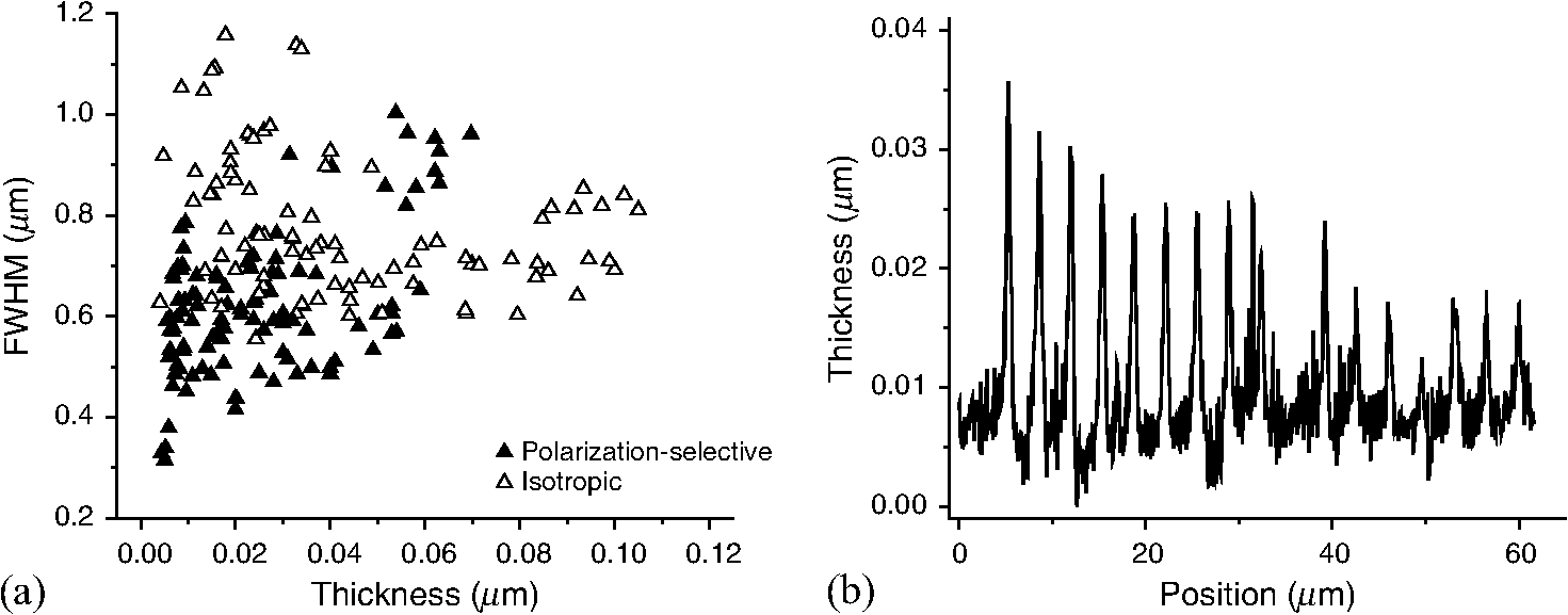
1.IntroductionLaser direct-writing refers to a technique that enables patterning in a surface or volume through spot-by-spot illumination by either moving the laser with a fixed sample stage or vice versa.1 This type of lithography enables formation of complex two- (2-D) and three-dimensional structures.2–13 As with any type of lithography, in laser direct-writing there is also a drive to increase the resolution. There have been different approaches to produce subdiffraction-limited spots, such as two-photon illumination 2,6 and two-color single-photon illumination.10,11 Here, an additional resolution enhancement method is proposed where a radially polarized laser beam is focused into a polarization-selective photoresist. There are several ways to generate radial polarization, such as interferometry,14,15 liquid crystal devices,16 optical fibers,17–19 space variant gratings,20,21 laser intracavity gratings,22,23 spatial light modulators,24 and wire grid polarizers (WGPs).25 WGP will be used here, because it offers high-quality performance in the near UV–VIS wavelength range, in particular for the wavelength of 405 nm, a wavelength that can be used for, e.g., optical disc mastering and laser writing. Focused radially polarized light exhibits a spot-like longitudinal polarization component combined with a doughnut-like transversal polarization component. The latter can be the dominant component inside current resist materials and will broaden the full-width-at-half-maximum (FWHM) of the printed spot. Additionally, it is known that the longitudinal component has an intensity distribution that is narrower compared to the Airy spot of a focused linearly polarized plane wave.26–30 Thus, solely by recording the longitudinal polarization component in a polarization-selective photoresist, one can obtain further enhancement of the resolution of laser direct-write lithography. Recently, a polarization-selective photoresist was developed by coaligning a dichroic photoinitiator, which is the polarization-selective component, in a reactive liquid crystalline (LC) monomer host.31 Uniaxial alignment of the mixture enables the selectivity of the photoresist toward a single polarization state of light that is parallel to the alignment. Upon illumination of this resist, an insoluble polymer network forms, i.e., it is a negative photoresist. In this work, a proof-of-concept for achieving higher resolution is shown using this resist material where the polarization-selective photoinitiator is aligned perpendicular to the substrate surface parallel to the mean direction of propagation of the incoming laser beam. 2.Experimental Setup2.1.Focused Radially Polarized Laser SetupThe setup to experimentally verify the size of the radially polarized focused spot in the photoresist is presented in Fig. 1. The 35-mW collimated diode laser beam of 405 nm and diameter of is guided through the first Glan-Laser prism polarizer GLP1. The nonpolarizing beamsplitter NBS1 splits the initial beam into two paths: radially and linearly polarized arms. We use a λ/4 plate WGP to shape circularly and subsequently radially polarized light and a vortex phase plate to acquire all polarization vectors in phase.32 The WGP, consisting of concentric aluminum cylinders on the glass substrate, was specifically designed and fabricated to form near UV–VIS high-quality radially polarized light, in particular at the wavelength of 405 nm. The radially or linearly polarized arm can be switched with a flip mirror. The radially/linearly polarized beam is focused by an NA = 0.9 (L2) objective onto the photoresist sample. The nonpolarizing beamsplitter NBS2 and the CCD camera are used to check that the laser is focused on the resist plane by observing the image of the focused spot on the camera. BS2 is removed during exposures. The sample with the photoresist is mounted on a closed-loop piezo-driven stage. The depth of focus of the polarized beam is slightly larger for radial than for linear polarization and becomes even larger inside the photoresist. Fig. 1Scheme of the setup to print focused radially/linearly polarized light arrays on isotropic and polarization-selective resists: 405-nm diode laser; collimation lens, to create a top hat beam profile; M1–M4, mirrors; FM, flipping mirror to switch between linearly and radially polarized arms; Pol1–Pol3, Glan-Laser polarizers; BS1, BS2, nonpolarizing beam splitters; /4, quarter-wave plate; WGP, wire grid polarizer; SPP, spiral phase plate; CCD, camera; high NA objective lens, NA = 0.9. 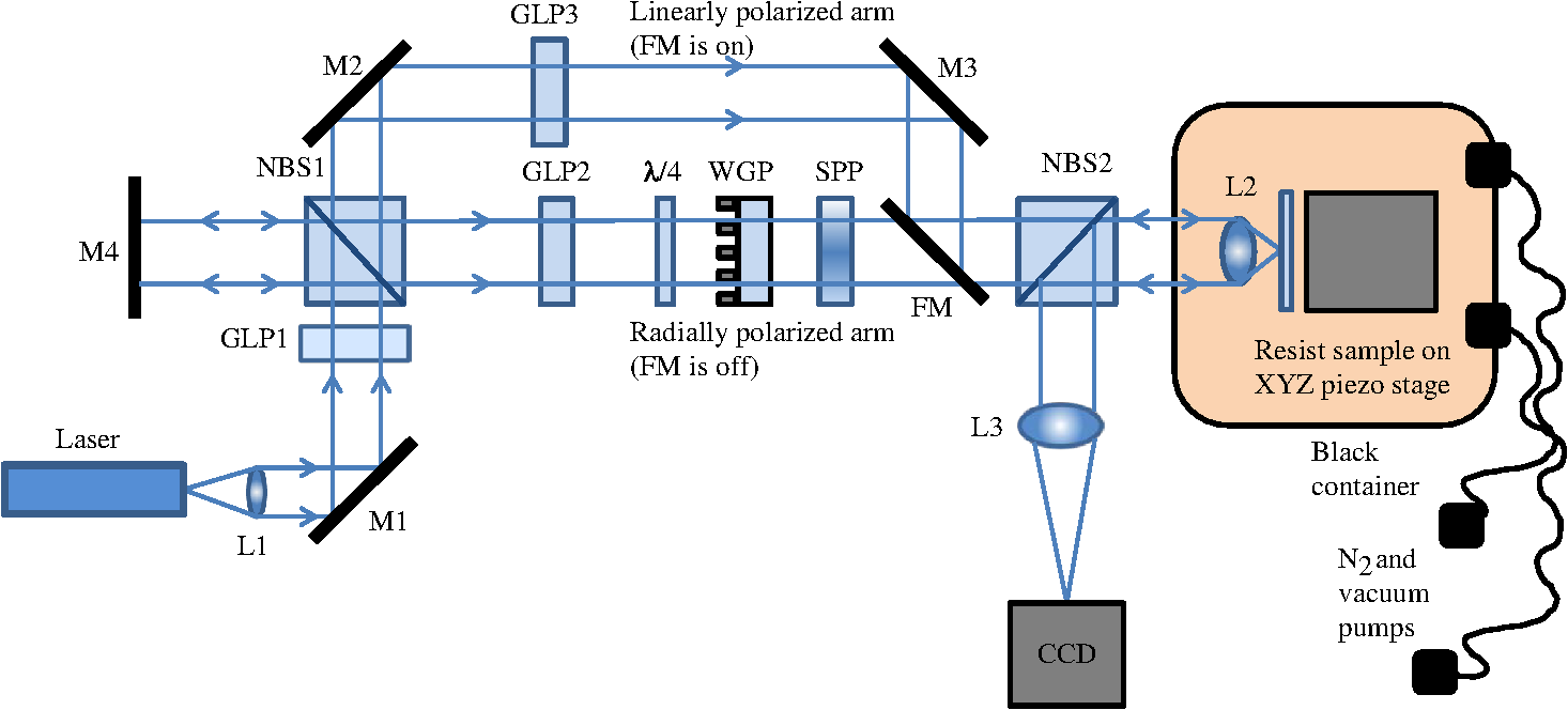 In this experiment, we use an automated procedure of 2-D array writing, which is implemented by means of a Lab View program simultaneously controlling the laser via pulse generator Tabor 8600 and the piezo stage position. Each spot in the printed 2-D array is associated with a certain exposure dose and through focus position, which are varied from spot to spot by moving the XYZ piezo stage. The focusing lens and piezo stage assembly are placed in a container that is flushed with nitrogen to create a low-oxygen environment to limit oxygen inhibition of the polymerization process. 2.2.PhotoresistThe components of the photoresist have been described elsewhere 31 and are also shown in Fig. 2. The LC host consists of a mixture of the LC host and cross-linker in a 5/1 weight ratio. The polarization-selective dichroic photoinitiator (1 wt. %) was supplied by Merck, and the inhibitor 4-methoxyphenol (0.5 wt. %) was supplied by Sigma–Aldrich. The inhibitor is added to increase the polarization-selectivity of the photoresist.31 Figure 2 shows the phase behavior of the two individual liquid crystal components. The phase transitions of the mixture are as follows: cooling from the isotropic phase, the mixture exhibits the cybotactic nematic phase at 145 °C; upon further cooling at 108 °C, it becomes smectic A; and at 54 °C it becomes smectic B. Under the exposure conditions at room temperature, the mixture is in its supercooled smectic B phase. Fig. 2Components of the polarization-selective photoresist. Cr, Crystalline; SmB, smectic B; SmA, smectic A; N, Nematic; and I, Isotropic. The numbers refer to the transition temperatures (°C) between the various liquid crystalline phases.32 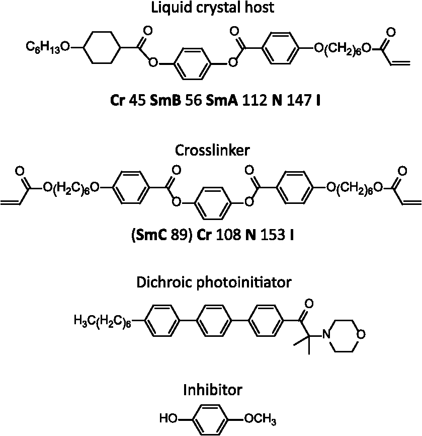 The photoresist was coated on cleaned glass, free of organic and inorganic contaminations, and handled in cleanroom conditions at the Kavli VLL cleanroom in Delft. The glass slides were placed in a 1/3-volume-based solution and heated for 10 min in a water bath of 70 °C. Subsequently, the slides were rinsed with demineralized water and kept in water before being rinsed in acetone and isopropanol. Finally, the glass slides were dried in a spin coater at 2000 rpm for approximately 1 min. A 12.5 wt. % solution of the LC photoresist in -xylene was prepared to coat the glass substrates. To ensure a homogeneous solution, it was mixed for 10 min at 70 °C and subsequently cooled to room temperature before spin coating at 1000 rpm for 90 s at an acceleration of 500 rpm to form layers of approximately 120 nm. After spin coating, the resist was placed on a hotplate at 60 °C for 30 s to ensure complete evaporation of -xylene. The samples were kept at least 1 h in nitrogen atmosphere before illuminating with focused radially polarized light. After illumination, a postexposure bake in nitrogen atmosphere was performed for 60 s at 80 °C to improve the mechanical stability of the polymer network. After cooling the photoresist down to room temperature, the photoresist was developed in cyclopentanone for 10 s to remove the unexposed areas, and subsequently dried with a nitrogen blow gun. The fabricated arrays after development were inspected with atomic force microscopy (AFM). To verify the dimensions of the spots, analyses of the same arrays were performed independently on two different AFMs, namely an NT-MDT Solver Next and a Bruker. 3.Results and Discussion3.1.Decomposition of Radially and Linearly Polarized Light into Longitudinal and Transverse Components inside the PhotoresistSimulations of radially and linearly polarized light propagation focused by a high NA = 0.9 lens inside the photoresist are carried out by means of homemade electromagnetic solver based on the Richards Wolf integrals.33 The interface effects due to the light propagation from the air into the photoresist have been fully taken into account in the calculations.34 Intensity profiles of radially and linearly polarized focused electric field strengths and its decomposition into longitudinal and transverse components are shown in Fig. 3. This graph shows a significant longitudinal component in case of radially polarized light [Fig. 3(a)], which is 1/3 of the total component, whereas it is ~1/10 times smaller than the total component in the case of focused linearly polarized light [Fig. 3(b)]. Fig. 3Intensity profiles of the longitudinal, transverse, and total electric field components focused inside the photoresist. These polarization components and the total sum of both components are shown for (a) radial and (b) linear polarization at the entrance pupil of the lens. The numerical aperture is NA = 0.9 and the average photoresist refractive index . 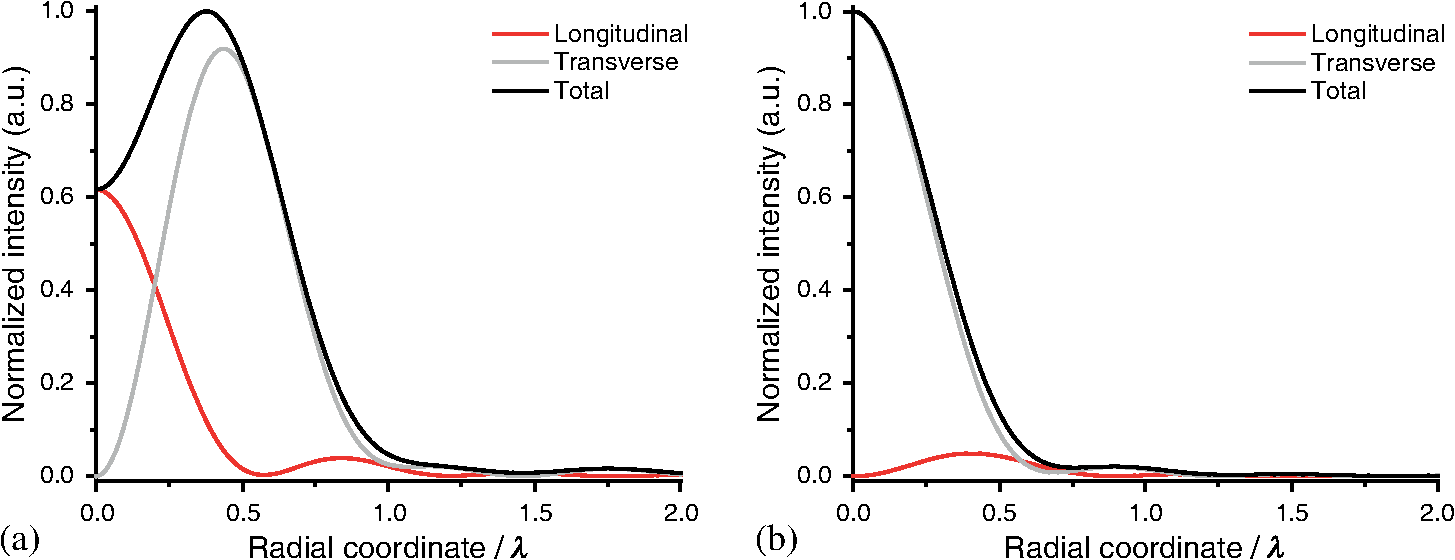 Ideally, the smallest possible FWHM of the spot is [see FWHM of longitudinal component in Fig. 3(a)]. This FWHM is 62% smaller in comparison with the FWHM of the total component. This occurs in the case of the polarization-selective resist, when radially polarized light has a sufficient exposure dose to print the longitudinal component. The transverse component is mainly transmitted and does not lead to formation of the polymer. 3.2.Polarization-Selectivity of the PhotoresistThe polarization parallel to the alignment of the LC photoresist is mainly absorbed by the resist. Previous work showed the polarization-selectivity of this type of LC photoresist toward linearly polarized light where the long axis of the rod-like LC molecules was parallel to the surface of the substrate, i.e., a planar alignment [Fig. 4(a) ].31 To promote absorption of the longitudinal polarization component, a homeotropic alignment of the photoresist is required where the long axis is orthogonal to the substrate’s surface [Fig. 4(b)]. The transversal polarization will be transmitted without inducing photochemical reactions. Fig. 4The photoresist consisting of a smectic B LC host (gray) and dichroic photoinitiator (white). (a) A planar alignment promotes the absorption of a single linear polarization state. (b) A homeotropic alignment promotes absorption of the longitudinal polarization component of light. In the latter case, both the polarization and propagation direction are along the gray arrow. 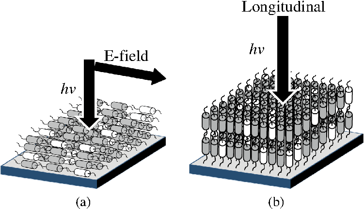 The LC photoresist self-organizes to the desired homeotropic alignment driven by surface tension. The homeotropic configuration was confirmed by polarization microscopy, which shows an extinguished image regardless the orientation of the crossed polarizers with respect to the sample axis. To confirm the required polarization-selective sensitivity of the LC photoresist, it was exposed with both focused radially and focused linearly polarized light. Upon the appropriate alignment, the resist shows higher sensitivity toward focused radially polarized light. A measure for the sensitivity of the resist can be expressed by plotting the remaining height after development as a function of the dose. This method can also be used to determine the contrast between the different states of polarizations during exposure of the LC photoresist. In Fig. 5(a), the height is plotted for a polarization-selective photoresist illuminated with focused radially and linearly polarized light. Both curves show a threshold after which a polymer film remains after development. The threshold is caused by the presence of the inhibitor, which delays the polymerization process.31 The threshold is approximately 100 and 250 nJ for radially and linearly polarized light, respectively, which means the LC photoresist shows selectivity toward absorbing the longitudinal component. This confirms the homeotropic alignment of the resist, which is needed to establish the polarization-selective polymerization. At equal dose, the thickness obtained with focused radial polarization is higher compared to linear polarization, which further confirms the preferential absorption of the longitudinal component. An important conclusion is to be made here: the range where only the longitudinal component is recorded by the resist is between 100 and 250 nJ, corresponding to layers up to 20 nm thick. Above this range, the photoresist records both the longitudinal and transversal components, widening the spot size, which is undesired. Fig. 5The thickness of the polymerized spot after development as a function of dose for (a) the polarization-selective and (b) the isotropic photoresist. 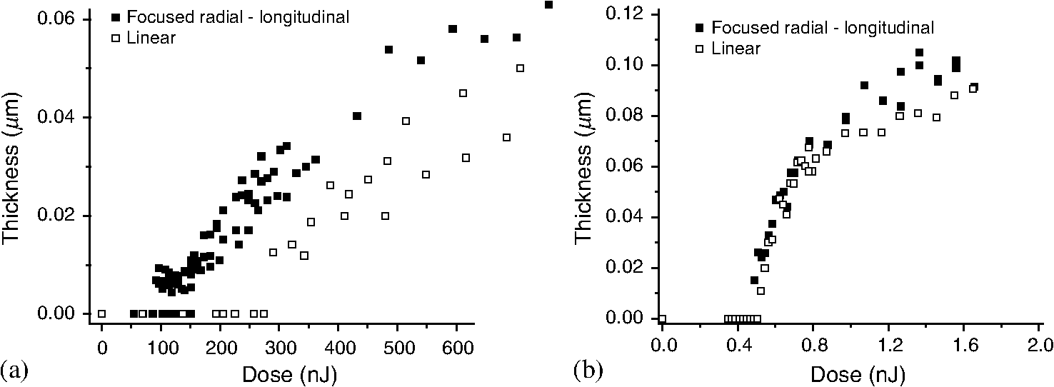 As a reference experiment, an additional LC photoresist was developed that is not polarization-selective, which will be referred to as the isotropic photoresist. In this resist, a commercially available photoinitiator that is not polarization-selective (Irgacure 819, Ciba specialty chemicals) substitutes for the dichroic photoinitiator. The rest of the LC resist formulation and processing remains unaltered. The thickness as a function of dose for this isotropic resist does not show a difference between the different polarization states, which means it is not polarization-selective [Fig. 5(b)]. 3.3.ResolutionFigure 6(a) shows an example of an AFM topography image of a developed array in the polarization-selective photoresist. Each column and row corresponds to a specific time of exposure and focus plane, respectively. In this array, the time of exposure was varied with 10 ms increments for each column and the focus plane was changed with 100 nm increments for each row. Figure 6(b) shows a profile of a column corresponding to a single time of exposure and a changing focal plane for each spot. As the through-focus is performed, the laser beam is focused into the negative LC photoresist to an increasingly small laser spot with a high-intensity density, which will result in a spot with larger thickness, as can be seen in Fig. 6(b). As the focus plane is changed further, moving out of focus, the laser spot becomes broader with a smaller intensity density, which leads to a smaller thickness. Therefore, the optimum focus is where the spot is the highest. The dimensions of the spots are determined for the optimum focus plane corresponding to the green-marked row [Figs. 6(a) and 6(c)]. This process was repeated for all analyzed arrays. Fig. 6(a) An example of an AFM topography image of a developed array in the polarization-selective photoresist where each row corresponds to a change of focus plane with 100 nm increments and between each column the time of exposure is changed with 10 ms increments. A profile view of the (b) red-marked column and (c) green-marked row. 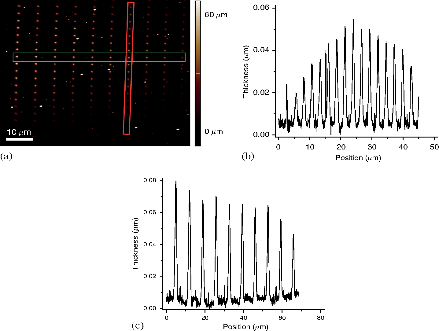 After development of the arrays, the spot dimensions were measured. The data in Fig. 7(a) provide the combined results of two independent AFM analyses. Figure 7(a) shows the FWHM as a function of the thickness for focused radially polarized light in the polarization-selective and the isotropic resists. It should be noted that the spread of the FWHM is large for spots that are less than 20 nm thick. This is due to the fact that for such thin layers, the roughness of the sample and the resolution of the AFM are not negligible; this can be seen in Fig. 7(b), which shows a profile of a typical array of spots that were exposed with low doses. However, as can be seen in Fig. 7(a), it is not significant; i.e., for small thicknesses, the FWHM is clearly smaller for the polarization-selective resist than the isotropic resist. The FWHM of the spots in the isotropic photoresist remains largely constant at roughly 800 nm for each thickness. This result is expected because this resist does not differentiate between the longitudinal and transversal polarization components; i.e., it records both components simultaneously. The polarization-selective photoresist shows an increase in FWHM with increasing thickness. At small spot thicknesses, which correspond to a low dose of between 100 and 250 nJ (Sec. 3.2), the resist records only the longitudinal component, which results in a small FWHM. As the applied dose increases above 250 nJ, the transversal polarization component is also recorded, which results in an increase of the FWHM. In the initial stage, the FWHM is approximately 350 nm, which is a reduction of 56% compared to the FWHM in the isotropic photoresist. This result matches with the simulations in Sec. 3.1, where a reduction of 62% was predicted. Another challenge will be to show a smaller FWHM of the radially polarized light in the polarization-selective resist in comparison with the FWHM of linearly polarized light in the isotropic resist. This type of polarization-selective resist can also be used to make narrow and tall pillars (thin needles), because the longitudinal field component of focused and spatially shaped radial polarization is narrower in lateral and longer in axial distribution. 4.ConclusionsIn this work, a proof-of-concept is shown where the FWHM can be reduced through the selective recording of the longitudinal polarization component of focused radially polarized light in a polarization-selective photoresist. This resist consists of a homeotropically aligned LC mixture with a polarization-selective photoinitiator. The FWHM of spots formed in this polarization-selective resist is up to 56% smaller compared to the isotropic resist, which nicely matches with simulations-based result of 62%. AcknowledgmentsThe authors are grateful to Joep Wijn from VDL ETG T&D for his help on the resist preparation and the focused radially polarized laser setup. The authors would also like to acknowledge the support of the Stichting voor Technische Wetenschappen (STW project 10727). Additionally, we acknowledge Merck for supplying the dichroic photoinitiator. ReferencesC. B. Arnold and A. Piqué,
“Laser direct-write processing,”
MRS Bull., 32
(1), 9
–15
(2007). http://dx.doi.org/10.1557/mrs2007.9 MRSBEA 0883-7694 Google Scholar
H. Jeon et al.,
“Chemical patterning of ultrathin polymer films by direct-write multiphoton lithography,”
J. Am. Chem. Soc., 133
(16), 6138
–6141
(2011). http://dx.doi.org/10.1021/ja200313q JACSAT 0002-7863 Google Scholar
S. Maruo and J. T. Fourkas,
“Recent progress in multiphoton microfabrication,”
Laser Photonics Rev., 2
(1–2), 100
–111
(2008). http://dx.doi.org/10.1002/lpor.200710039 Google Scholar
T. W. Lim et al.,
“Selective ablation-assisted two-photon stereolithography for effective nano- and microfabrication,”
Appl. Phys. A, 103
(4), 1111
–1116
(2011). http://dx.doi.org/10.1007/s00339-010-6051-z APAMFC 0947-8396 Google Scholar
A. Goswami et al.,
“Polymer microfabrication by scanning based microstereolithography: optical design and material functionality,”
Rev. Sci. Instrum., 83
(9), 095003
(2012). http://dx.doi.org/10.1063/1.4750975 RSINAK 0034-6748 Google Scholar
S. Kawata et al.,
“Finer features for functional microdevices—micromachines can be created with higher resolution using two-photon absorption,”
Nature, 412
(6848), 697
–698
(2001). http://dx.doi.org/10.1038/35089130 Google Scholar
Y. Cao et al.,
“High-photosensitive resin for super-resolution direct-laser-writing based on photoinhibited polymerization,”
Opt. Express, 19
(20), 19486
–19494
(2011). http://dx.doi.org/10.1364/OE.19.019486 OPEXFF 1094-4087 Google Scholar
Z. Sekkat and S. Kawata,
“Laser nanofabrication in photoresists and azopolymers,”
Laser Photonics Rev., 8
(1), 1
–26
(2014). http://dx.doi.org/10.1002/lpor.201200081 Google Scholar
M. Malinauskas et al.,
“Ultrafast laser nanostructuring of photopolymers: a decade of advances,”
Phys. Rep., 533
(1), 1
–31
(2013). http://dx.doi.org/10.1016/j.physrep.2013.07.005 PRPLCM 0370-1573 Google Scholar
J. T. Fourkas and J. S. Petersen,
“2-Colour photolithography,”
Phys. Chem. Chem. Phys., 16
(19), 8731
–8750
(2014). http://dx.doi.org/10.1039/c3cp52957f PPCPFQ 1463-9076 Google Scholar
T. F. Scott et al.,
“Two-color single-photon photoinitiation and photoinhibition for subdiffraction photolithography,”
Science, 324
(5929), 913
–917
(2009). http://dx.doi.org/10.1126/science.1167610 SCIEAS 0036-8075 Google Scholar
A. C. Sullivan, M. W. Grabowski and R. R. McLeod,
“Three-dimensional direct-write lithography into photopolymer,”
Appl. Opt., 46
(3), 295
–301
(2007). http://dx.doi.org/10.1364/AO.46.000295 APOPAI 0003-6935 Google Scholar
J. -H. Lee et al.,
“25th anniversary article: ordered polymer structures for the engineering of photons and phonons,”
Adv. Mater., 26
(4), 532
–569
(2014). http://dx.doi.org/10.1002/adma.201303456 ADVMEW 0935-9648 Google Scholar
S. C. Tidwell, D. H. Ford and W. D. Kimura,
“Generating radially polarized beams interferometrically,”
Appl. Opt., 29
(15), 2234
–2239
(1990). http://dx.doi.org/10.1364/AO.29.002234 APOPAI 0003-6935 Google Scholar
H. Chien-Yuan et al.,
“Simple triangular path interferometer for generation of an inhomogeneously polarized beam,”
Jpn. J. Appl. Phys., 48
(9R), 092402
(2009). JJAPA5 0021-4922 Google Scholar
M. Stalder and M. Schadt,
“Linearly polarized light with axial symmetry generated by liquid-crystal polarization converters,”
Opt. Lett., 21
(23), 1948
–1950
(1996). http://dx.doi.org/10.1364/OL.21.001948 OPLEDP 0146-9592 Google Scholar
T. Grosjean, D. Courjon and M. Spajer,
“An all-fiber device for generating radially and other polarized light beams,”
Opt. Commun., 203
(1–2), 1
–5
(2002). http://dx.doi.org/10.1016/S0030-4018(02)01122-7 OPCOB8 0030-4018 Google Scholar
S. Ramachandran, P. Kristensen and M. F. Yan,
“Generation and propagation of radially polarized beams in optical fibers,”
Opt. Lett., 34
(16), 2525
–2527
(2009). http://dx.doi.org/10.1364/OL.34.002525 OPLEDP 0146-9592 Google Scholar
C. Weibin et al.,
“Generating cylindrical vector beams with subwavelength concentric metallic gratings fabricated on optical fibers,”
J. Opt., 13
(1), 015003
(2011). http://dx.doi.org/10.1088/2040-8978/13/1/015003 JOOPDB 0150-536X Google Scholar
G. M. Lerman et al.,
“Light transmission through a circular metallic grating under broadband radial and azimuthal polarization illumination,”
Opt. Lett., 36
(20), 3972
–3974
(2011). http://dx.doi.org/10.1364/OL.36.003972 OPLEDP 0146-9592 Google Scholar
Z. Bomzon, V. Kleiner and E. Hasman,
“Formation of radially and azimuthally polarized light using space-variant subwavelength metal stripe gratings,”
Appl. Phys. Lett., 79
(11), 1587
–1589
(2001). http://dx.doi.org/10.1063/1.1401091 APPLAB 0003-6951 Google Scholar
M. A. Ahmed et al.,
“Radially polarized 3 k W beam from a CO2 laser with an intracavity resonant grating mirror,”
Opt. Lett., 32
(13), 1824
–1826
(2007). http://dx.doi.org/10.1364/OL.32.001824 OPLEDP 0146-9592 Google Scholar
T. Moser et al.,
“Intracavity generation of radially polarized CO2 laser beams based on a simple binary dielectric diffraction grating,”
Appl. Opt., 45
(33), 8517
–8522
(2006). http://dx.doi.org/10.1364/AO.45.008517 APOPAI 0003-6935 Google Scholar
M. Bashkansky, D. Park and F. K. Fatemi,
“Azimuthally and radially polarized light with a nematic SLM,”
Opt. Express, 18
(1), 212
–217
(2010). http://dx.doi.org/10.1364/OE.18.000212 OPEXFF 1094-4087 Google Scholar
Z. Ghadyani et al.,
“Concentric ring metal grating for generating radially polarized light,”
Appl. Opt., 50
(16), 2451
–2457
(2011). http://dx.doi.org/10.1364/AO.50.002451 APOPAI 0003-6935 Google Scholar
S. Quabis et al.,
“Focusing light to a tighter spot,”
Opt. Commun., 179
(1), 1
–7
(2000). http://dx.doi.org/10.1016/S0030-4018(99)00729-4 OPCOB8 0030-4018 Google Scholar
R. Dorn, S. Quabis and G. Leuchs,
“Sharper focus for a radially polarized light beam,”
Phys. Rev. Lett., 91
(23), 233901
(2003). http://dx.doi.org/10.1103/PhysRevLett.91.233901 PRLTAO 0031-9007 Google Scholar
Y. Ma and R. Wu,
“Characterizing polarization properties of radially polarized beams,”
Opt. Rev., 21
(1), 4
–8
(2014). http://dx.doi.org/10.1007/s10043-014-0002-4 1340-6000 Google Scholar
T. Grosjean, D. Courjon and C. Bainier,
“Smallest lithographic marks generated by optical focusing systems,”
Opt. Lett., 32
(8), 976
–978
(2007). http://dx.doi.org/10.1364/OL.32.000976 OPLEDP 0146-9592 Google Scholar
H. P. Urbach and S. F. Pereira,
“Field in focus with a maximum longitudinal electric component,”
Phys. Rev. Lett., 100
(12), 123904
(2008). http://dx.doi.org/10.1103/PhysRevLett.100.123904 PRLTAO 0031-9007 Google Scholar
M. P. Van et al.,
“Polarization-selective polymerization in a photo-crosslinking monomer film,”
RSC Adv., 4
(107), 62499
–62505
(2014). http://dx.doi.org/10.1039/C4RA11574K Google Scholar
Q. Zhan,
“Cylindrical vector beams: from mathematical concepts to applications,”
Adv. Opt. Photonics, 1
(1), 1
–57
(2009). http://dx.doi.org/10.1364/AOP.1.000001 Google Scholar
B. Richards and E. Wolf,
“Electromagnetic diffraction in optical systems II. Structure of the image field in an aplanatic system,”
Proc. R. Soc. A, 253 258
–379
(1959). http://dx.doi.org/10.1098/rspa.1959.0200 Google Scholar
A. S. v. d. Nes et al.,
“Calculation of the vectorial field distribution in a stratified focal region of a high numerical aperture imaging system,”
Opt. Express, 12
(7), 1281
–1293
(2004). http://dx.doi.org/10.1364/OPEX.12.001281 OPEXFF 1094-4087 Google Scholar
BiographyMy-Phung Van received her MSc degree in chemical engineering from Eindhoven University of Technology in 2009. During her graduation project, she studied the network formation of polymer-inorganic composite coatings. After receiving her MSc degree, she started working at Océ Technologies, where she studied the crystallization behavior of hotmelt ink before starting her PhD in May 2010. In January 2015, she successfully defended her thesis titled ”Polarization-Selective Optical Lithography” at Eindhoven University of Technology. Katsiaryna Ushakova completed her BSc and MSc degrees in optics from Belarusian State University in Minsk, Belarus. In 2011, she joined the optics research group of Delft University of Technology, The Netherlands, as a PhD for the project “High-resolution optical lithography using unconventional polarization states of light.” Her research interests are in classical optics; clean room fabrication and inspection techniques; and simulation models in optics with applications in lithography, metrology, and high-numerical optical systems. Cees W. M. Bastiaansen spent parts of his research career in the industry (DSM Research, The Netherlands) and at the ETHZ (Zürich, Switzerland). Nowadays, he is part time (0.8 FTE) at Eindhoven University of Technology, The Netherlands, and part time at the University of London, Queen Mary, UK. His main research interests include structure–property relationships in polymers with a focus on static and dynamic optical, electronic, and mechanical properties. A special emphasis in his work is devoted to anisotropic systems based on rigid and flexible macromolecular systems. Silvania F. Pereira got her PhD in the USA in the field of quantum optics. She did her postdoc at the University of Constance, Germany, after receiving the Humboldt fellowship. She also worked as a postdoc at the University of Leiden, The Netherlands. Currently, she is an associate professor at Delft University of Technology, The Netherlands. Her research is in classical optics, with applications in lithography, metrology, and high-numerical optical systems. H. Paul Urbach spent most of his research career in Philips Research in Eindhoven, The Netherlands, where he applied diffraction theory to many different optical problems. In most topics, the interaction of light with structures of the order of a wavelength is important and therefore rigorous electromagnetic models were developed and applied. Since 2000, he has been a part-time professor at Delft University of Technology, The Netherlands, and since 2008, he has been a full-time professor at that university. Dirk J. Broer is a materials scientist who specializes in molecular structured soft matter. From 1973 to 2010, he worked at Philips Research Laboratories at electronics, data storage, communication hardware, and display optics. Since 1996, he has been a part-time professor and since 2010, he has been a full-time professor at Eindhoven University, expanding his field of expertise to illumination systems, solar energy, organic semiconductors, lithography, and soft actuators. In 2015, he joined the Institute of Complex Molecular Systems (ICMS), Eindhoven, The Netherlands. |