|
|
1.IntroductionAs the major data storage provider so far, the hard disk drive (HDD) industry based on magnetic recording is facing a tremendous challenge from the areal density growth. Due to the well-known superparamagnetic effect,1 current magnetic recording technique, perpendicular recording, may not be able to carry HDD too far beyond an areal density of (1 T). Next-generation magnetic recording technologies, such as heat-assisted magnetic recording2 and bit-patterned media (BPM),3 are under intense research and development at industry laboratories now. BPM, consisting of physically isolated magnetic single domains, put forward very stringent lithography requirements on the pattern density of , the pattern uniformity of bit size sigma, and the pattern addressability of bit position sigma.4 All those are very difficult to be satisfied simultaneously even using state-of-the-art “top-down” lithography techniques such as 193-nm immersion lithography, extreme ultraviolet lithography, or electron-beam lithography. Directed self-assembly (DSA) using block copolymers (BCPs) provides a versatile approach for nanopatterning at unprecedented resolution or pattern density.5–9 The control of long-range order and addressability of BCP nanodomains has been solved by applying commensurate pre-patterns with either chemical10–12 or topographical13 contrast. In the consideration of DSA for BPM fabrication, a comprehensive collection of all pattern information on a BPM disk is definitely needed first. The patterns on a BPM disk can be divided into two categories. One is located at regions called data zones, which consists of globally densely packed dot arrays with long-range order. The other is located at regions called servo zones. The servo patterns provide address information of each track and every bit in the data zones for the recording head to locate during data reading and writing. For this purpose, alternative magnetic and nonmagnetic areas are designed in the servo zone. In our servo design, locally densely packed dot arrays with short-range order are pursued. Here, using a spherical BCP, polystyrene-block-polydimethylsiloxane (PS--PDMS), we investigate several kinds of pre-patterns to generate various DSA patterns in response to different pattern layout requirements in the data zone and the servo zone, respectively. The effectiveness of each DSA pattern is evaluated. As a characteristic of HDD design, skew compatibility of spherical BCPs is also quantified. Furthermore, pattern transfer experiment at such high-density level as 1 and 2 T is performed. Pattern fidelity is analyzed. Finally, successful fabrication of 2 T magnetic media implies great potential of DSA technology for ultrahigh-density BPM application. 2.Experimental Procedure2.1.MaterialsPS--PDMS BCPs, PS homopolymer, and PS brush materials were purchased from Polymer Source, Inc., Dorval, Canada. Various spherical PS--PDMS BCP systems are listed in Table 1 with detailed information such as molecular weight (), polydispersity (PDI), and natural domain spacing (). Specifically, spherical BCPs at 1.3 and 2 T were prepared by blending BCP with PS homopolymer. The PS homopolymer has and . PS brush materials are hydroxyl terminated PS with various from 3.7 to 40k. Imprint resist materials were purchased from Molecular Imprints, Inc., Austin. Hydrogen silsesquioxane (HSQ) material was purchased from Dow Corning as XR-1541 electron-beam resist. Table 1PS-b-PDMS BCP materials.
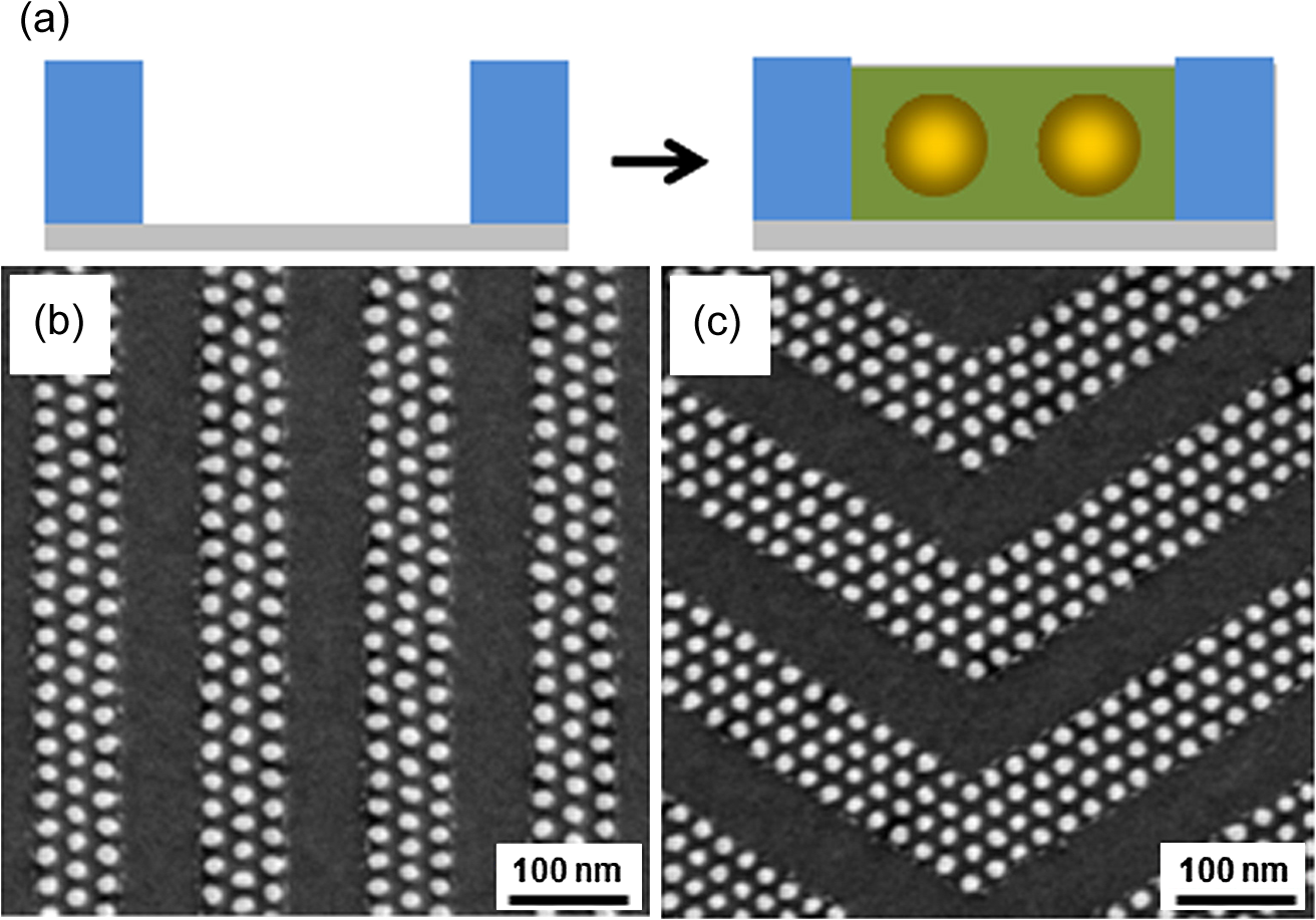
2.2.Sample PreparationTwo-dimensional (2-D) hole-tone pre-patterns with feature heights (hole depths) of were prepared by either rotary-stage electron-beam lithography or nanoimprint lithography. 2-D pillar-tone pre-patterns with feature heights (pillar heights) of 30 nm were generated by -stage electron-beam lithography using HSQ resists. A PS brush layer was thermally grafted onto the HSQ pillar patterns to provide a uniform wetting layer. One-dimensional (1-D) trench pre-patterns with feature heights of 30 nm were created by nanoimprint lithography and thermally grafted with a PS brush layer. PS--PDMS thin films were spin-coated onto pre-patterns and thermal annealed at 170°C for 24 h. Then, reactive-ion etch (RIE) was applied to remove a thin layer of PDMS on the top surface prior to RIE for removing unprotected PS blocks so as to reveal oxidized PDMS dots. In pattern transfer experiment, a thin Cr layer was always sputtered onto quartz substrates prior to any pre-patterning or DSA process. Chlorine RIE was applied for transferring BCP patterns into Cr. Then, RIE was applied for quartz etch. Ion-beam etching of magnetic materials was performed on an argon ion miller. 2.3.CharacterizationBCP patterns, quartz dot patterns, and magnetic dot patterns were characterized by using a scanning electron microscope (SEM) operated at 10 keV and a transmission electron microscope operated at 200 keV. BCP patterns were imaged after RIE as described before. A 3-nm thick Cr was deposited on quartz samples to minimize charging effects, while its effect on dot size/spacing estimation was not excluded in image analysis. Magnetic loops were measured by an in-house magnetometer. As for image analysis, the dot was defined as a circle, either inscribed within the dot or circumscribed around the dot’s external contour. The dot size was defined as the dot diameter. The dot spacing was defined as the center-to-center distance between two neighboring dots in the -direction. The distribution was defined as a quotient of the standard deviation divided by the mean. Each image includes about 1000 dots for a total of at least five images analyzed per pattern. The resolution was chosen so that each dot has . 3.Results and Discussion3.1.DSA in the Data Zone Using 2-D Hole-Tone Pre-PatternsPreviously, we developed a method of using 2-D hole-tone pre-patterns created by -stage electron-beam lithography to guide the self-assembly of spherical PS--PDMS.14 Density multiplication factors of to and pattern densities of 1.3 to 3.8 T have been achieved via that approach. Here, we utilized a rotary-stage electron-beam writer so as to generate 2-D hexagon arranged hole-tone pre-patterns in a thin PS brush layer over a much larger area (2-mm wide ring at a radius of 20 mm or so). Or in another way, a similar type of pre-patterns was created in a thin imprint resist layer by nanoimprint lithography using a mold fabricated by rotary-stage electron-beam lithography. Nonetheless, both kinds of 2-D hole-tone pre-patterns share almost the same pattern information such as a hexagon pattern lattice, a low pattern density (i.e., ), and a small feature height (i.e., the hole depth is ). Figure 1(a) shows the schematic of DSA of spherical BCPs on a shallow hole-tone pre-pattern with pitch doubling or density quadrupling. A 1 T PS--PDMS dot pattern was generated by using a pre-pattern at 0.25 T [Fig. 1(b)]. Similarly, a 2 T PS--PDMS dot pattern was formed by using a pre-pattern at 0.5 T [Fig. 1(c)]. After image analysis of BCP dot patterns at 1 T, it shows narrow distributions of dot spacings (in the -direction or circumferential direction) and dot sizes, both within 5% [Fig. 1(d)]. When the BCP pattern density increases to 2 T, the dot spacing distribution (5.5%) is still reasonably tight while the dot size distribution ramps up to 6.7%. These findings are not surprising, since the fluctuations of BCP dot spacings or dot positions are not only determined by the BCP material property or DSA thermodynamics but also restricted by the pre-pattern while the BCP dot sizes are affected less by the pre-pattern. From this point of view, the larger distribution comes from dot sizes instead of dot spacings as observed from both 1 T samples and 2 T samples. Fig. 1Directed self-assembly (DSA) in data zone using 2-D hole-tone pre-patterns. (a) Schematic of DSA of a spherical spherical block copolymer (BCP) using a shallow hole-tone pre-pattern. (b) 1 T BCP dot pattern using a 0.25 T pre-pattern. (c) 2 T BCP dot pattern using a 0.5 T pre-pattern. (d) BCP dot spacing (in the -direction) and size distribution at 1 and 2 T. Size/spacing distribution is calculated as a quotient of the standard deviation divided by the mean. 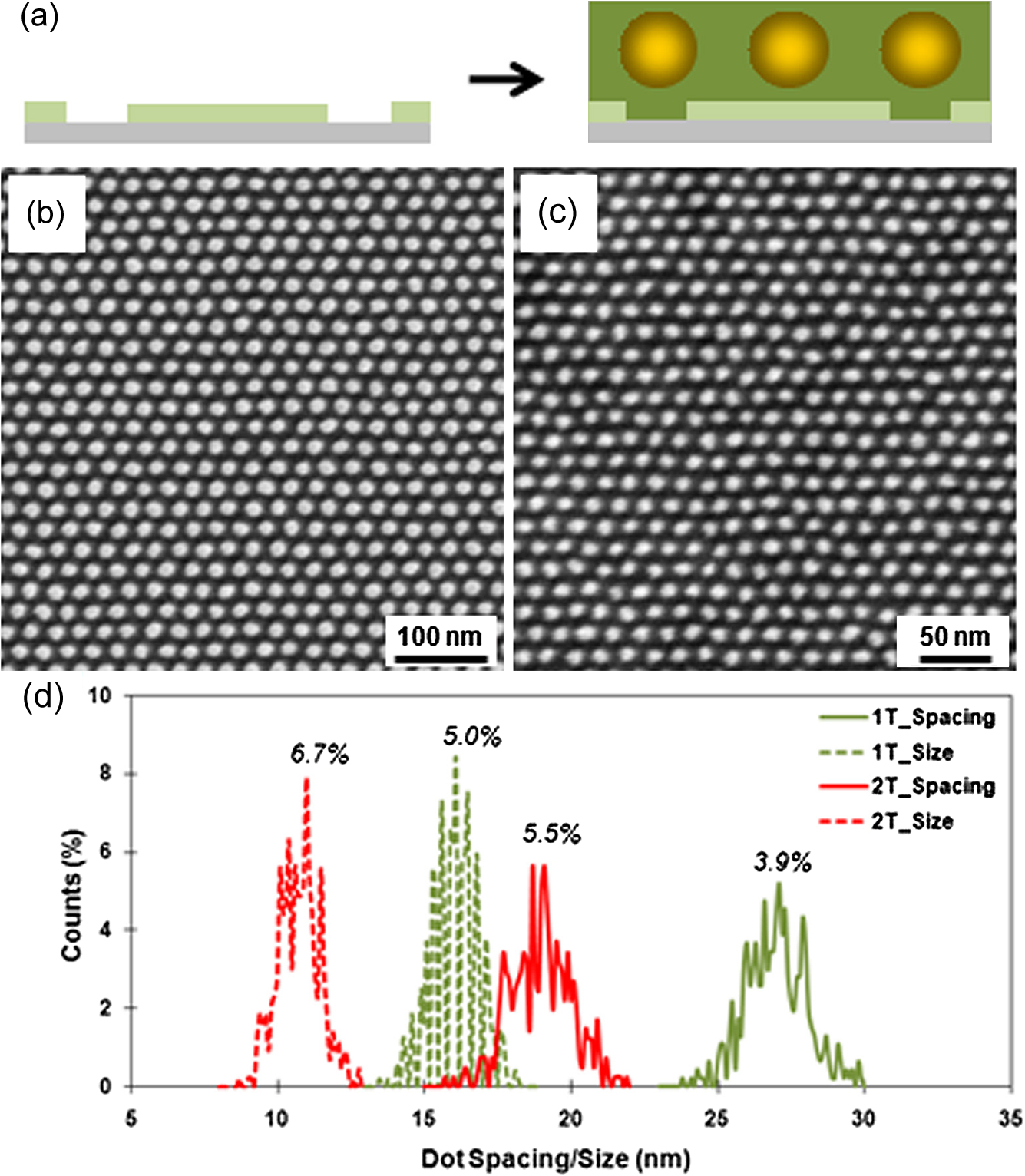 3.2.DSA in the Data Zone Using 2-D Pillar-Tone Pre-PatternsBesides 2-D hole-tone pre-patterns, 2-D pillar-tone pre-patterns have also been tested for DSA of spherical PS--PDMS. Similar to a previous report,13 2-D HSQ pillar patterns were created by electron-beam lithography using HSQ resists. The advantage of this approach is that the size of HSQ pillars can be controlled to due to the high resolution property of HSQ as a molecular resist. To provide a uniform surface wetting property for DSA of spherical PS--PDMS, a polymer brush layer is needed first. Here, PS was selected as the brush layer material due to better wetting property for PS--PDMS thin films during spin-coating, compared to PDMS. Figure 2(a) shows the schematic of DSA of spherical BCPs on a pillar-tone pre-pattern with pitch tripling. In our experiment, the PS brush length was found to play an important role on the DSA pattern quality. The BCP used in this study has a natural domain spacing of 24 nm (corresponding to 1.3 T), mainly consisting of a PS--PDMS with a molecular weight of 13.5 to 4k. The HSQ pre-pattern period is designed as 72 nm, three times of . Several hydroxyl terminated PS brushes with different molecular weights were applied as the wetting layers. When the molecular weight of PS brushes is 3.7k, the center-to-center distance between HSQ pillars and closest BCP dots, as indicated by the arrow in Fig. 2(b), is less than , although a hexagon exists as evidenced by the Fourier transfer (FT) analysis. When the molecular weight of PS brushes is 10 k [Fig. 2(c)], close to the molecular weight of PS blocks in the copolymer (13.4k), an almost perfect hexagon lattice appears with uniform dot spacings. When the molecular weight of PS brushes increases to 20k [Fig. 2(d)], the outer interference set in FT analysis indicates periodic BCP dot arrays without long-range order. When the molecular weight of PS brushes increases further to 40k [Fig. 2(e)], much larger than that of PS blocks in the copolymer, periodic BCP dot patterns disappear as indicated by the dim outer interference set in FT analysis. As can be seen from the above, a polymer brush with similar molecular weight to corresponding blocks in the copolymer is critical for achieving uniform DSA patterns using 2-D pillar-tone pre-patterns. Fig. 2DSA in data zone using 2-D pillar-tone pre-patterns. (a) Schematic of DSA of a spherical BCP using a pillar-tone pre-pattern, surface-modified by a polystyrene (PS) brush layer (not shown). Brush length effect on DSA pattern: molecular weight of PS brush is 3.7k (b), 10k (c), 20k (d), and 40k (e). Insets in (b) to (e) show corresponding FT analysis. The label in (b) points to the gap between hydrogen silsesquioxane (HSQ) pillars and closest BCP dots. is 24 nm, whereas is 72 nm. 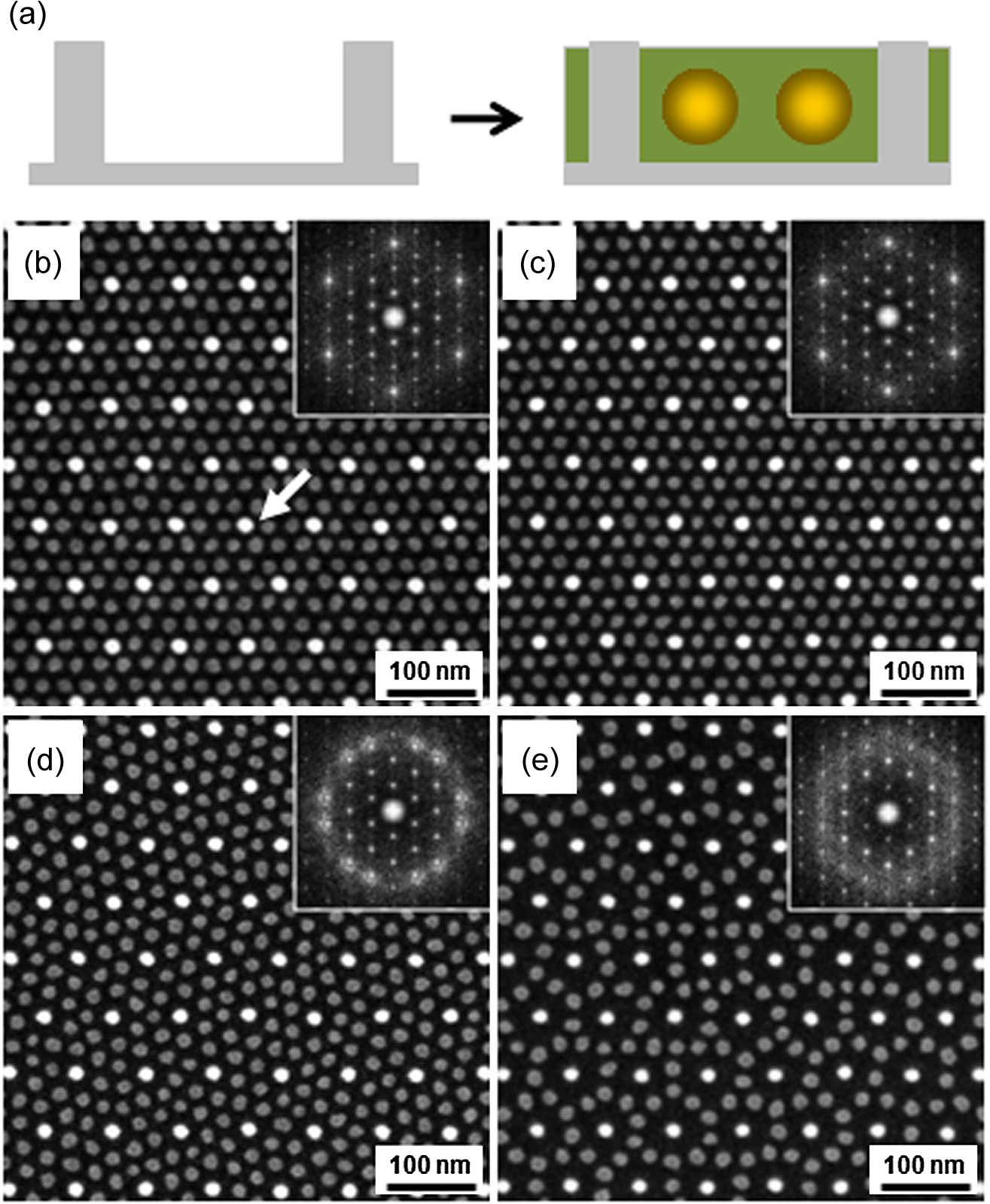 3.3.DSA in the Servo Zone Using 1-D Trench Pre-PatternsServo zones require pattern layouts different from globally addressable and densely packed dot arrays in data zones. Alternative patterned and unpatterned regions are preferred. In this regard, graphoepitaxy15 utilizing topographical pre-patterns have advantages over chemo-epitaxy;16 since, the regions occupied by the topographical pre-patterns are left void usually. Graphoepitaxy of spherical,17 cylindrical,18 and lamellar19 BCPs has been extensively studied before. Figure 3(a) shows the schematics of DSA of a spherical BCP using a 1-D trench pre-pattern. As long as certain commensurability conditions are satisfied,17 BCP dot arrays with integral row numbers are aligned to the trench sidewall. And locally densely packed dot arrays are segregated by unpatterned regions. Some typical servo patterns such as a preamble area and a burst area are shown in Fig. 3(b) and 3(c), respectively. Besides, more complex servo patterns are also compatible with DSA of BCPs as long as properly designed pre-patterns are provided.20 And it should be noted that the DSA patterns in servo zone are not necessarily aligned to those in data zone. 3.4.Skew Compatibility of Spherical BCPsConcerns on skew compatibility of DSA to a BPM system originate from the mechanical design of an HDD. An HDD consists of several recording media disks and several recording heads. Inside a recording head, an actuator arm and suspension of the rotary actuator are collinear making the movement of the slider follow an arc and not a straight line. To match the motion of the slider or the recording head, the bits on a BPM disk are arranged slightly different at different radiuses. In a hexagonal close-packed array of spherical or cylindrical BCPs, the BCP lattice needs to deviate from the regular hexagon. A skew angle21 is pre-designed into the pre-pattern to test the skew compatibility of spherical PS--PDMS as used here. The pre-pattern was made of HSQ pillars, which has a period of 48 nm, two times of . A PS brush layer was grafted to the topographical pre-pattern prior to BCP thin film coating, to provide a uniform wetting property. As shown in Fig. 4(a), the BCP dots interpolate evenly between HSQ pillars, at zero skew angle. At some higher skew angles [Fig. 4(b) and 4(c)], the BCP dot arrays are able to follow the skew pre-patterns by presenting skew DSA patterns. But at a skew angle as large as 12 deg, the phenomenon is broken due to insufficient self-adjustment capability of polymer chains. A compatible skew angle of up to was also observed before when a shallow 2-D hole-tone pre-pattern was used for the same BCP, which indicates the skew compatibility of a spherical BCP system is not limited by the pre-pattern type but constrained by the intrinsic stretching and compressing capability of BCP molecular and thermodynamics. Fig. 4DSA using pillar-tone skew pre-patterns. (a) DSA of a spherical BCP on a pre-pattern with zero skew. (b) DSA of a spherical BCP on a pre-pattern with 4 deg skew. (c) DSA of a spherical BCP on a pre-pattern with 8 deg skew. (d) DSA of a spherical BCP on a pre-pattern with 12 deg skew. is 24 nm, whereas is 48 nm. 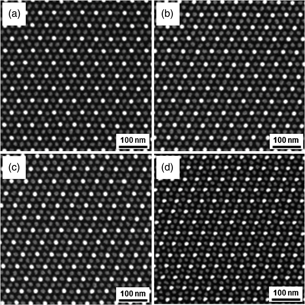 3.5.Pattern Transfer into Quartz and Magnetic MediaUsually, a BCP template is not useful until it can be used as a mask for pattern transfer into functional materials. In a typical process flow of BPM fabrication, the BCP patterns are transferred into a nanoimprint mold first, which is made of quartz for UV imprinting. In our experiment, PS--PDMS nanopatterns were etched into a Cr layer first by using chlorine RIE. Cr dots were then applied as hard masks for quartz etch using RIE. Quartz dot patterns at 1 and 2 T, respectively, are shown in Fig. 5(a) and 5(b). Image analysis shows that after pattern transfer into quartz both the dot size distribution and the dot spacing distribution are well maintained at 1 T [Fig. 5(c)]. But at 2 T, both distributions are broadened. Especially, the dot spacing distribution ramps up significantly from 5.5% [Fig. 1(d)] to 8.2% [Fig. 5(c)], well out of the design tolerance of 5%.4 Future work will focus on improving pattern fidelity after pattern transfer at such a high pattern density as 2 T or above. Fig. 5Pattern transfer into quartz. (a) 1 T quartz dot pattern. (b) 2 T quartz dot pattern. (c) Quartz dot spacing (in the -direction) and size distribution at 1 and 2 T. Size/spacing distribution is calculated as a quotient of the standard deviation divided by the mean.  Soon after a nanoimprint mold is obtained, efforts are put on how to imprint the high-density nanopattern into a thin resist layer and then transfer it into magnetic media. A so-called tone-reversal process was applied to convert the hole-tone resist pattern into a pillar-tone silicon oxide pattern. In this tone-reversal process, an HSQ layer was spin-coated onto the nanoporous imprint resist pattern first. Then, a RIE process was applied to remove those HSQ materials on top, leaving HSQ posts separated by surrounding imprint resists. After the removal of remaining imprint resist matrix by RIE, a silicon oxide (oxided HSQ) dot pattern was obtained. This silicon oxide dot pattern can be transferred into a magnetic multilayer on a disk by ion-beam etch. Long-range ordered magnetic dot arrays at 2 T [Fig. 6(a)] were obtained across the disk. Clear gap between adjacent dots was observed in cross sectional TEM [Fig. 6(b)] indicating good physical isolation. The flat top and a large sidewall angle represent well-defined magnetic dot profiles. As high coercivity as was measured from the magnetic loop [Fig. 6(c)] showing excellent single-domain behavior in such high-density magnetic media. Fig. 6Pattern transfer into 2 T magnetic media. (a) Top-view scanning electron microscopy (SEM) of magnetic dots. (b) Cross-sectional transmission electron microscopy (TEM) of magnetic dots. (c) Magnetic loop of 2 T media showing a high coercivity of kOe. The -axis is a magnetic field in the unit of Oe, and the -axis is unitless intensity. 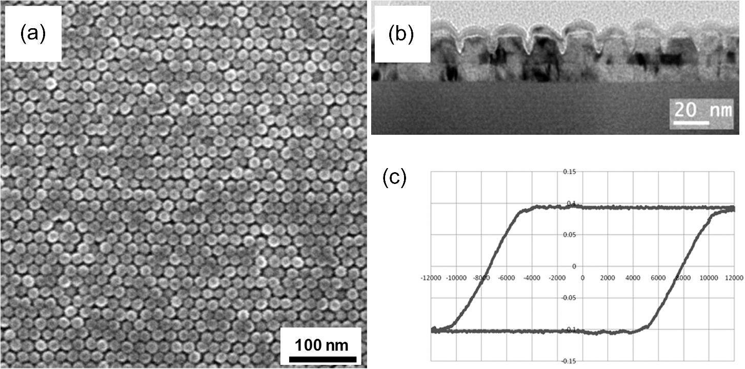 4.ConclusionsDSA of spherical PS--PDMS is successfully implemented to the fabrication of BPM templates and media, consisting of both data patterns of globally densely packed dot arrays and servo patterns of locally densely packed dot arrays segregated by unpatterned regions. Different types of pre-patterns are applied and evaluated for DSA in either data zones or servo zones. Skew compatibility of spherical BCPs is quantified and the results agree with a previous study using the same BCP but a different pre-pattern. High-fidelity pattern transfer from BCP nanotemplates to quartz and magnetic alloys indicates great potential of the DSA technology to enable next-generation magnetic storage media fabrication. AcknowledgmentsThe authors thank Yautzong Hsu, Hongying Wang, and Michael R. Feldbaum for helpful experiments and discussions. ReferencesC. A. Ross,
“Patterned magnetic recording media,”
Annu. Rev. Mater. Res., 31 203
–235
(2001). http://dx.doi.org/10.1146/annurev.matsci.31.1.203 ARMRCU 1531-7331 Google Scholar
W. A. Challeneret al.,
“Heat-assisted magnetic recording by a near-field transducer with efficient optical energy transfer,”
Nat. Photon., 3
(4), 220
–224
(2009). http://dx.doi.org/10.1038/nphoton.2009.26 1749-4885 Google Scholar
B. D. TerrisT. Thomson,
“Nanofabricated and self-assembled magnetic structures as data storage media,”
J. Phys. D, 38
(12), R199
–R222
(2005). http://dx.doi.org/10.1088/0022-3727/38/12/R01 JPAPBE 0022-3727 Google Scholar
H. J. Richteret al.,
“Recording potential of bit-patterned media,”
Appl. Phys. Lett., 88
(22), 222512
–222514
(2006). http://dx.doi.org/10.1063/1.2209179 APPLAB 0003-6951 Google Scholar
D. J. C. Herr,
“Update on the extensibility of optical patterning via directed self-assembly,”
Future Fab. Intl., 20 82
–86
(2006). Google Scholar
J. Banget al.,
“Block copolymer nanolithography: translation of molecular level control to nanoscale patterns,”
Adv. Mater., 21
(47), 4769
–4792
(2009). http://dx.doi.org/10.1002/adma.200803302 ADVMEW 0935-9648 Google Scholar
M. Parket al.,
“Block copolymer lithography: periodic arrays of holes in 1 square centimeter,”
Science, 276
(5317), 1401
–1404
(1997). http://dx.doi.org/10.1126/science.276.5317.1401 SCIEAS 0036-8075 Google Scholar
C. B. Tanget al.,
“Evolution of block copolymer lithography to highly ordered square arrays,”
Science, 322
(5900), 429
–432
(2008). http://dx.doi.org/10.1126/science.1162950 SCIEAS 0036-8075 Google Scholar
S. Parket al.,
“Macroscopic 10-terrabit-per-square-inch arrays from block copolymers with lateral order,”
Science, 323
(5917), 1030
–1033
(2009). http://dx.doi.org/10.1126/science.1168108 SCIEAS 0036-8075 Google Scholar
S. O. Kimet al.,
“Epitaxial self-assembly of block copolymers on lithographically defined nanopatterned substrates,”
Nature, 424
(6947), 411
–414
(2003). http://dx.doi.org/10.1038/nature01775 NATUAS 0028-0836 Google Scholar
J. Y. Chenget al.,
“Dense self-assembly on sparse chemical patterns: rectifying and multiplying lithographic patterns using block copolymers,”
Adv. Mater., 20
(16), 3155
–3158
(2008). http://dx.doi.org/10.1002/adma.v20:16 ADVMEW 0935-9648 Google Scholar
R. Ruizet al.,
“Density multiplication and improved lithography by directed block copolymer assembly,”
Science, 321
(5891), 936
–939
(2008). http://dx.doi.org/10.1126/science.1157626 SCIEAS 0036-8075 Google Scholar
I. Bitaet al.,
“Graphoepitaxy of self-assembled block copolymers on two-dimensional periodic patterned templates,”
Science, 321
(5891), 939
–943
(2008). http://dx.doi.org/10.1126/science.1159352 SCIEAS 0036-8075 Google Scholar
S. Xiaoet al.,
“A novel approach to addressable 4 teradot/in2 patterned media,”
Adv. Mater., 21
(24), 2516
–2519
(2009). http://dx.doi.org/10.1002/adma.v21:24 ADVMEW 0935-9648 Google Scholar
R. A. Segalmanet al.,
“Graphoepitaxy of spherical domain block copolymer films,”
Adv. Mater., 13
(15), 1152
–1155
(2001). http://dx.doi.org/10.1002/(ISSN)1521-4095 ADVMEW 0935-9648 Google Scholar
P. A. R. Delgadilloet al.,
“Implementation of a chemo-epitaxy flow for directed self-assembly on 300-mm wafer processing equipment,”
J. Microlith. Microfab., 11
(3), 031302
(2012). http://dx.doi.org/10.1117/1.JMM.11.3.031302 Google Scholar
J. Y. Chenget al.,
“Nanostructure engineering by templated self-assembly of block copolymers,”
Nat. Mater., 3
(11), 823
–828
(2004). http://dx.doi.org/10.1038/nmat1211 NMAACR 1476-1122 Google Scholar
S. Xiaoet al.,
“Graphoepitaxy of cylinder-forming block copolymers for use as templates to pattern magnetic metal dot arrays,”
Nanotechnology, 16
(7), S324
–S329
(2005). http://dx.doi.org/10.1088/0957-4484/16/7/003 NNOTER 0957-4484 Google Scholar
R. Gronheidet al.,
“Frequency multiplication of lamellar phase block copolymers with grapho-epitaxy directed self-assembly sensitivity to prepattern,”
J. Micro/Nanolithog. MEMS MOEMS, 11
(3), 031303
(2012). http://dx.doi.org/10.1117/1.JMM.11.3.031303 Google Scholar
Y. Kamataet al.,
“Fabrication of ridge-and-groove servo pattern consisting of self-assembled dots for 2.5 tb/in 2 bit patterned media,”
IEEE Trans. Magn., 47
(1), 51
–54
(2011). http://dx.doi.org/10.1109/TMAG.2010.2077274 IEMGAQ 0018-9464 Google Scholar
S. Xiaoet al.,
“Aligned nanowires and nanodots by directed block copolymer assembly,”
Nanotechnology, 22
(30), 305302
–305309
(2011). http://dx.doi.org/10.1088/0957-4484/22/30/305302 NNOTER 0957-4484 Google Scholar
|